CHAPTER 5. OPERATING INSTRUCTIONS
HF-2500A HIGH FREQUENCY WELD CONTROL
990-371 5-17
Section VI. Pre-Weld Check
Note: The Pre-Weld Check function is used to detect misaligned or missing parts before the weld is
performed. Therefore, the Pre-Weld Check function should only be programmed after the welding
schedule has been developed. The welding schedule includes the time and energy settings as well as the
electrode force required to produce strong, consistent welds.
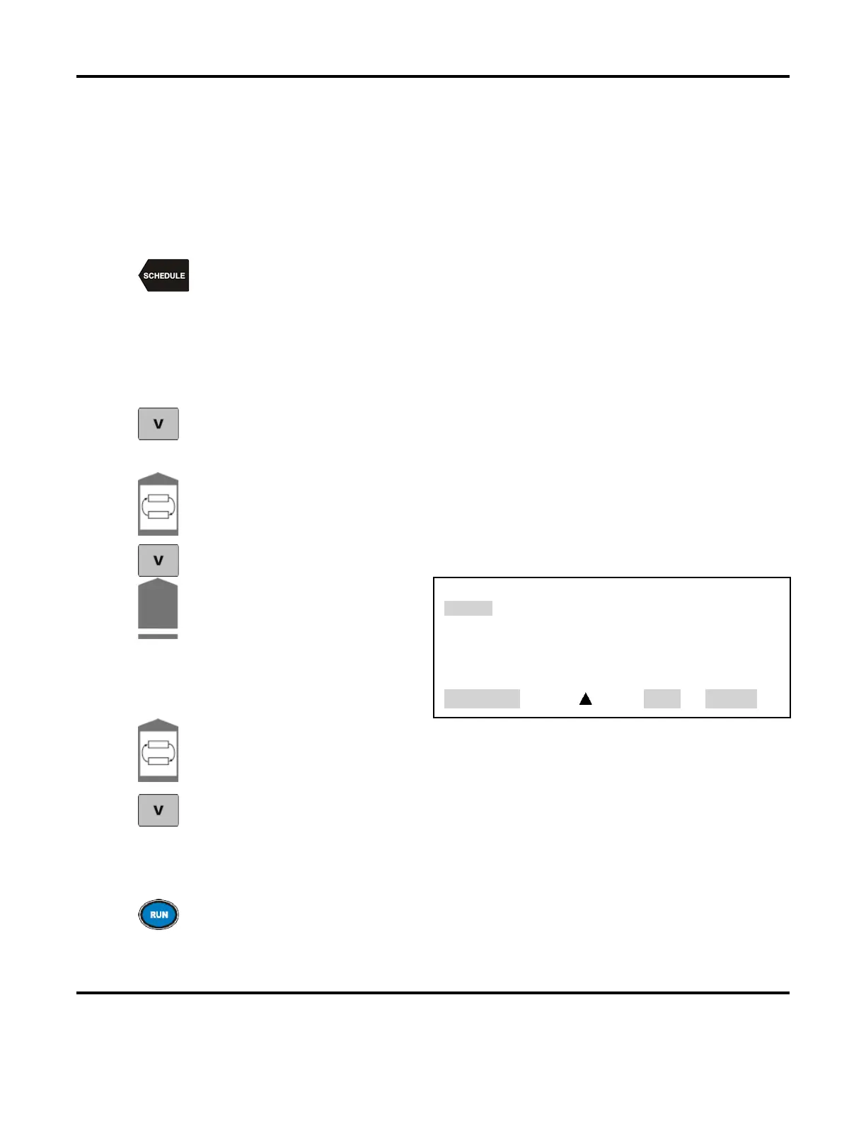
Press the SCHEDULE key, then select a Weld Schedule using either the ▲▼ arrows or
the numeric keypad.
Program the second pulse as required to produce strong, consistent welds. Then, program the
first pulse for
Constant Current
operation. Program the first pulse current level to
approximately 10% of the second pulse current. Program the first pulse upslo
pe time to 1
ms
and first pulse weld time to 2
ms. Program 2
ms of cool time between the pulses. Make a few
welds and verify that the welds are strong and consistent.
From the MONITOR keys section on the front panel, press the voltage V key and observe
the peak voltage reading of the first pulse. Make several more welds and observe the
range of first pulse peak voltage readings from weld to weld.
Press the Pulse 1 weld key to highlight the upper limit field for the weld period. Use the
numeric keypad to enter the upper limit
value for the Pulse 1 weld period. Program a
voltage level that is slightly higher than the voltages observed in step 3 above.
Press the voltage V key to save the setting as an upper voltage limit.
Press the COOL weld period key.
This will bring up the PULSE 1
OUT OF LIMITS ACTION
screen.
Select 2. STOP WELD
PULSE 1 OUT OF LIMITS ACTION
1. none
2. STOP WELD
3. INHIBIT PULSE 2
4. PART CONDITIONER (Stop Pulse1)
NUMBER Select, Page, RUN or MENU
.
Toggle the Pulse 1 weld key to highlight the lower
limit field for the Pulse 1 weld period.
Use the numeric keypad to enter a lower limit
value with a voltage level that is slightly
lower than the voltages observed in step 3 above.
Press the voltage V key to save the setting as a lower voltage limit.
. Make several more welds and verify that under normal circumstances, the limits
are not reached
and the welds are not aborted. If the limits are reached under normal welding conditions, adjust
the levels and times of the upper and lower voltage limits accordingly.
Return to the RUN screen and make several welds. Observe that under normal conditions,
the welds are not aborted, and that consistent, strong welds can be produced.