CHAPTER 3: SYSTEM CONFIGURATION
HF-2500A HIGH FREQUENCY WELD CONTROL
3-16 990-371
Run State
RUN
key puts the Power Supply in
the run state. In the run state, the screen shows a
trace that represents your programmed parameters
for a given weld schedule. You may select a
different weld schedule to be programmed with
the
SCHEDULE key and keypad, or with the up and
down arrows. Then, you may program squeeze
time, up slope, weld time, weld energy, down slope and cool time with the trace segment selector keys.
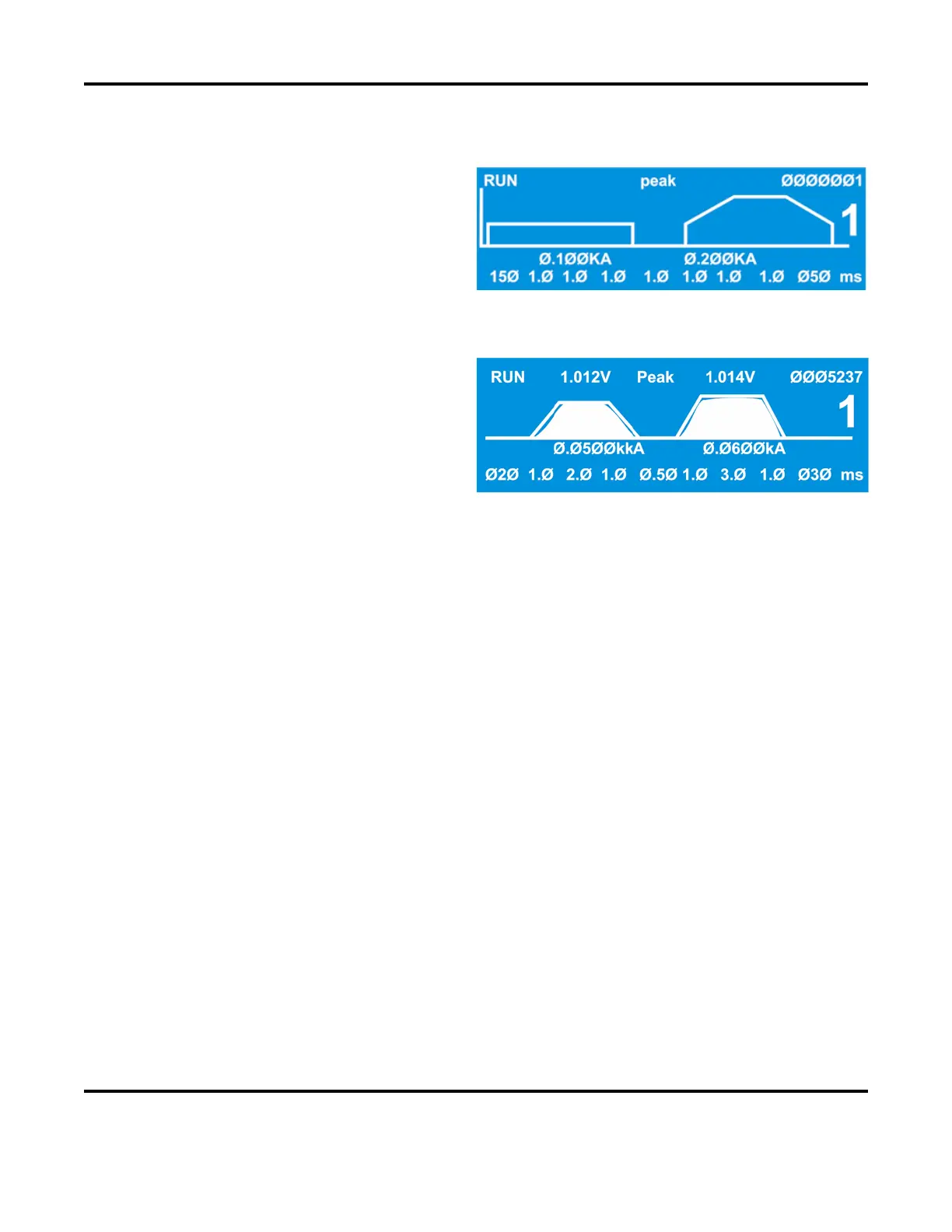
In the example on the right, the top line of the
screen shows that the
Power Supply is in the RUN
ltage at the voltage sense lead
PULSE 1 weld period was
volts, the monitor is set for displaying peak
voltage (rather than average voltage), the voltage
at the voltage sense input
connection for the
PULSE 2 weld period was 1.014 volts, and the total
weld count since the weld counter was last reset is 5,237.
The weld profile trace is an analog display of the electrical parameters programmed with the weld period
selector keys. When the weld is initiated, a profile of the actual weld energy delivered during the weld
cycle, or both weld cycles, will be overlaid on the trace.
The large-type number 1 is the selected weld schedule.
The values
0.050 kA and 0.060 kA below the trace are respectively the weld current values programmed
for
PULSE 1 and PULSE 2 weld periods. You may optionally program weld energy in volts or kilowatts
with the energy units selection keys.
Use the time/energy selector keys to toggle between the weld energy value field and the bottom line of
text, which is the weld period time selection field. Use the weld period selector keys to enable the weld
periods for programming, and use the numeric pad keys for entering time values in milliseconds.
See Chapter 5, Operating Instructions for application-related descriptions of the weld schedule profile.