CHAPTER 5. OPERATING INSTRUCTIONS
HF-2500A HIGH FREQUENCY WELD CONTROL
990-371 5-21
Section VIII. Weld Stop
NOTE: The Weld Stop function is similar to the Pre-Weld Check function, as both are used to detect
missing or misaligned parts. Both functions are used to stop the weld when a specific current, voltage,
or power level is reached. The Weld Stop function stops the weld in the actual welding pulse; the Pre-
Weld Check uses a small pre-pulse to stop the weld. The Weld Stop function should only be programmed
after a welding schedule, which produces acceptable results, has been developed. The welding schedule
includes the time and energy settings as well as the electrode force setting. In the following steps, a
Constant Current weld is used as an example to show how the Weld Stop function is programmed.
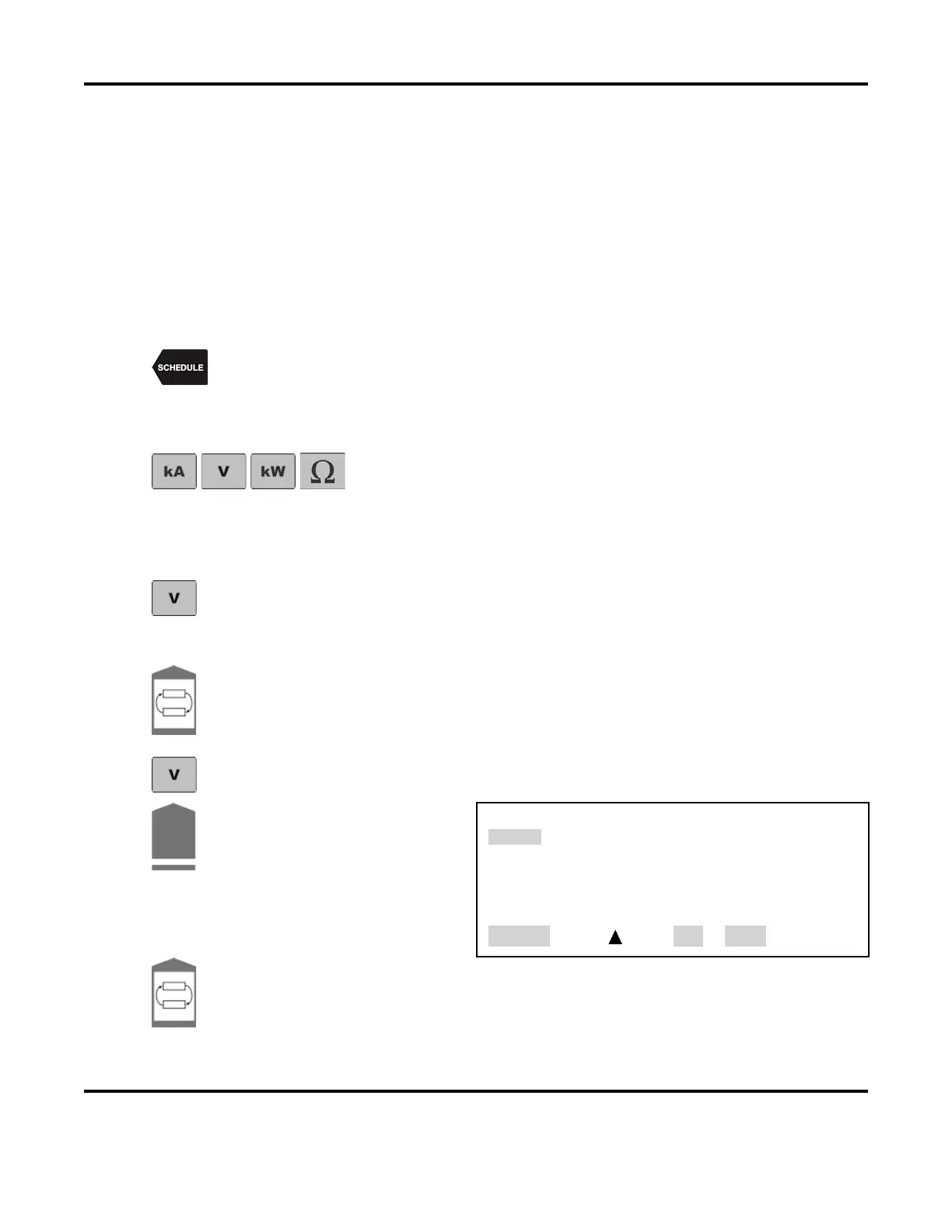
SCHEDULE
key, then select a Weld Schedule using either the ▲▼ arrows or
the numeric keypad.
Program a single pulse for Constant Current operation as required to make strong, consistent
welds. Make a few welds and verify that the welds are acceptable.
From the MONITOR keys section on the front panel, press the kA
(current), V (voltage), kW (power), and Ω
observe the resulting waveforms.
NOTE: You can toggle between PEAK and AVERAGE readings by pressing the
PEAK/AVERAGE key.
Press the V (voltage) key and observe the voltage waveform.
Observe the peak and average readings on the voltage monitor screen. Make several more
welds and observe the range of voltage readings from weld to weld.
Press the Pulse 1 weld key to highlight the upper limit field for the weld period. Use the
numeric keypad to enter the upper limit
value for the Pulse 1 weld period. Program an
upper voltage limit that is slightly above the peak voltage readings observed
above.
Press the voltage V key to save the setting as an upper voltage limit.
Press the COOL weld period key.
This will bring up the PULSE 1
OUT OF LIMITS ACTION
screen.
Select 2. STOP WELD
PULSE 1 OUT OF LIMITS ACTION
1. none
2. STOP WELD
3. INHIBIT PULSE 2
4. PART CONDITIONER (Stop Pulse 1)
NUMBER Select, Page, RUN or MENU
Toggle the Pulse 1 weld key to highlight the lower
limit field for the Pulse 1 weld period.
Use the numeric keypad to enter a lower limit
value with a voltage level that is slightly
lower than the voltages observed in step 3 above.