CHAPTER 5. OPERATING INSTRUCTIONS
HF-2500A HIGH FREQUENCY WELD CONTROL
5-16 990-371
NOTE: For more details on this process, see Resistance Set in Chapter 4, Using Feedback
Modes and Weld Monitoring.
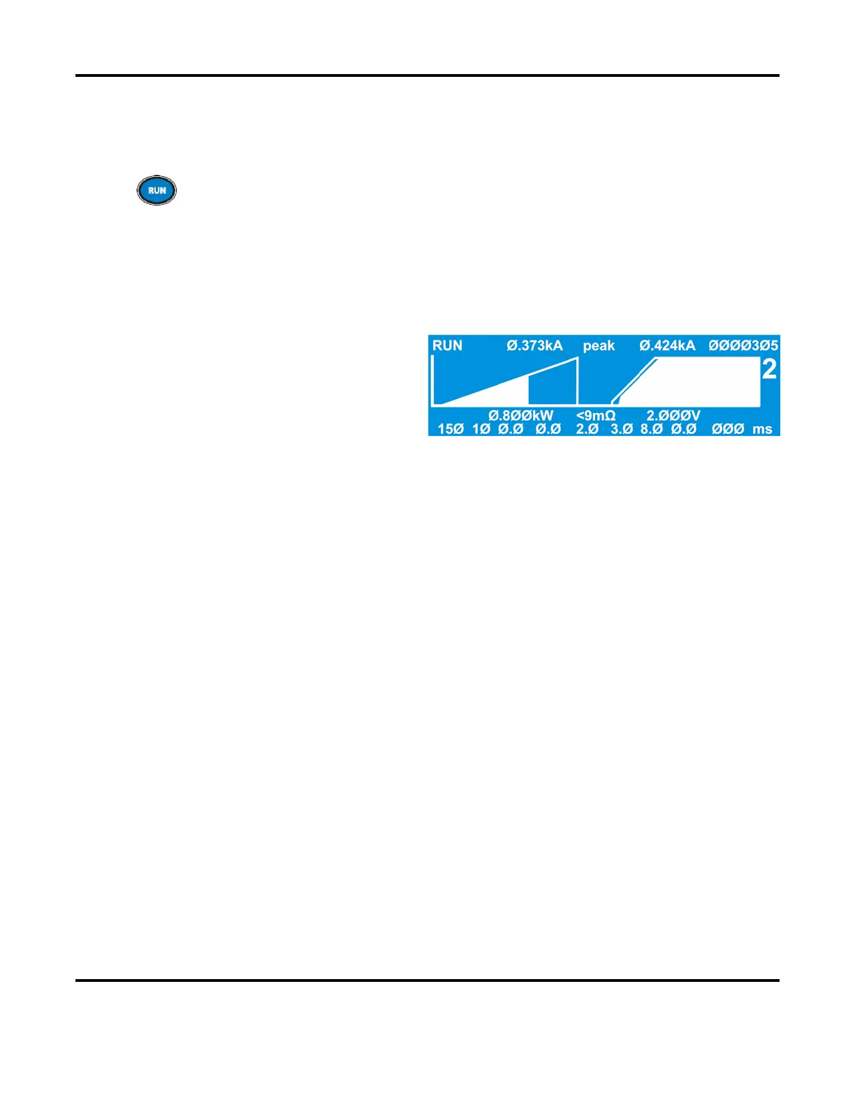
Since different levels of resistance require different amounts of time to reach the current
limit, return to the RUN
screen and extend the programmed weld time (usually double the
time works). This will ensure that there will be enough time for the current to rise and
reach the limit, even with wide variations in initial resistance.
The power supply terminates the first pulse when your programmed current is reached. A low
resistance
part will reach the current limit sooner and the pulse will terminate early. A
part will require more time before the resistance decreases and current can flow.
Program your second welding pulse as
normal to achieve a strong weld.
Constant voltage is recommended for
round parts and constant current for flat
parts. An upslope may be required to
restrict the current flow early in the
second pulse and avoid weld spl
ash.