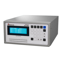
The AMADA MU-100A is a head controller designed to manage the vertical movement of a welding head while monitoring weld force and displacement. It offers a comprehensive suite of features for precision welding applications, including measurement, control, data management, and compatibility with various welding machines and head types.
Function Description:
The primary function of the MU-100A is to control the up and down movement of the welding head, ensuring precise application of weld force and accurate measurement of displacement. This control is time-based, managing the valve of the welding head. The controller supports several measurement modes for both displacement and force sensors, allowing for flexible application depending on the welding requirements.
For displacement measurement, the controller offers Synchro Mode (SYNC(0)), Sequence Mode (SQNC(1)), Sample Hold 1 Mode (SH1(2)), Sample Hold 2 Mode (SH2(3)), and Sample Hold 3 Mode (SH3(4)).
- Synchro Mode (SYNC(0)) is designed for applications where both load cell and displacement sensor are connected. It measures Before Weld Work after Squeeze-Time and Before Weld Force, outputting a WELD START signal if within limits. After Weld-Time and Hold-Time, it measures After Weld Work and Displacement, outputting a GOOD signal if within limits. This mode ignores the Force Measure Mode setting.
- Sequence Mode (SQNC(1)) is for displacement sensor-only applications. It measures Before Weld Work after Squeeze-Time, outputs a WELD START signal, and then measures After Weld Work and Displacement after Hold-Time, outputting a GOOD signal if within limits.
- Sample Hold 1 Mode (SH1(2)) is also for displacement sensor-only use. It measures Before Weld Work only when the ST-DISP signal is input, outputting a GOOD signal if within limits.
- Sample Hold 2 Mode (SH2(3)) is for displacement sensor-only applications where the origin is set upon ST-DISP signal input. After Squeeze time, it outputs a WELD START signal, and then measures After Weld Work after Weld-Time, outputting a GOOD signal if within limits. This mode is suitable for stopping welding at a set displacement after internally resetting displacement to zero.
- Sample Hold 3 Mode (SH3(4)) is for displacement sensor-only applications where workpiece thickness and displacement are measured when the ST-DISP signal is input twice. Measurement and judgment can be controlled via PLC.
For force measurement, the controller provides Sequence Mode (SQNC(0)), Sample Hold 1 Mode (SH1(1)), Sample Hold 2 Mode (SH2(2)), and Tangential Mode (TANG(3)). These modes are used when the load cell is connected without a displacement sensor, and the Disp Measure Mode is set to an item other than SYNC(0).
- Sequence Mode (SQNC(0)) measures Before Weld Force after Squeeze-Time, outputs a WELD START signal, and then measures After Weld Force after Hold-Time, outputting a GOOD signal if within limits.
- Sample Hold 1 Mode (SH1(1)) measures Before Weld Force only when the ST-FORCE signal is input, outputting a GOOD signal if within limits.
- Sample Hold 2 Mode (SH2(2)) starts welding when the set weld force value is reached, and measures the maximum force during welding.
- Tangential Mode (TANG(3)) starts welding when the set weld force value is reached, and measures After Weld Force at a specified point (Weld(0) or Hold(1)).
The MU-100A also includes data communication capabilities, allowing for the transmission of measurement data and settings to a PC via Ethernet, RS-232C, or RS-485 interfaces. This enables centralized management of welding parameters and results.
Important Technical Specifications:
- Power Supply: Single-phase, 100 to 240 V AC ±10% (50/60 Hz), 0.5 A.
- Fuse Rating: 250V1A.
- Operating Environment: Temperature 5 to 40°C, Humidity 90% or less.
- Storage Environment: 0 to 55°C.
- Outline Dimensions: 109 (H) × 200 (W) × 268 (D) mm (not including projection).
- Mass: 3.3 kg.
- Control Modes:
- Displacement sensor + Load cell: SYNC.
- Displacement sensor: SQNC, SH1, SH2, SH3.
- Load cell: SQNC, SH1, SH2, TANG.
- Time Setting: Squeeze time, Weld time, Hold time.
- Time Setting Range: 0 to 9.999 sec.
- Number of Schedules: Up to 127 can be stored.
- Counter: Start counter, Preset counter.
- Communication Interfaces: Ethernet, RS-232C, RS-485.
- Displacement Sensor:
- Applicable sensor: Incremental type.
- Measurement range: 0 to ±50.000 mm.
- Upper/lower limit setting range: 0 to ±99.999 mm.
- Resolution: 1 μm.
- Measurement items: Before-welding workpiece thickness, After-welding workpiece thickness, Displacement.
- Level outputs: 3.
- Analog output: 1 (output delay time: approx. 1.5 ms).
- Origin setting: Valid.
- Accuracy: ±0.015 mm (for 30-mm displacement sensor or shorter), ±0.025 mm (for 50-mm displacement sensor).
- Load Cell:
- Measurement range, Resolution:
- 1.00 to 20.00 N, 2.50 to 50.00 N: 0.01N increments.
- 10.0 to 200.0 N, 25.0 to 500.0 N: 0.1N increments.
- 100 to 2000 N, 250 to 5000 N: 1N increment.
- 500 to 10000 N: 10N increments.
- Upper/lower limit setting range:
- 0 to 20.00 N, 0 to 50.00 N: 0.01N increments.
- 0 to 200.0 N, 0 to 500.0 N: 0.1N increments.
- 0 to 2000 N, 0 to 5000 N: 1N increment.
- 0 to 10000 N: 10N increments.
- Applicable rated output: 0 to 2 mV/V.
- Measurement items: Before-welding force, After-welding force.
- Level outputs: 3.
- Analog output: 1 (output delay time varies according to the Force Sampling setting).
- Zero setting: Valid.
- Accuracy: Full scale ±3%.
Usage Features:
- User Interface: The front panel features an LCD for displaying measured values and menus, IN/OUT lamps for interface status, and dedicated keys for schedule setting (SCH), zero setting (ZSET), WELD START signal output (WELD), and HEAD signal output (HEAD). A numerical keypad, direction keys, ENT key, RES key, FUN key, and MONI key provide comprehensive control and navigation.
- Schedule Management: Up to 127 schedules can be stored, allowing for quick recall and application of different welding conditions. The controller supports copying schedules from one axis to another, simplifying setup for multi-axis systems.
- Measurement Data Management: Measurement data and settings can be transmitted to a PC, facilitating data analysis, archiving, and remote configuration.
- Welding Head Control: The HEAD key allows manual control of the welding head, enabling output of SV11, SV12, SV13, SV21, SV22, and SV23 signals for lowering the head during off-sequence periods.
- Error Handling: The RES key resets errors, and the controller provides warning outputs for various error conditions, such as preset errors, load cell over-range, STOP input open, CPU malfunctions, and memory errors.
- Customizable Display: Users can select which items are displayed on the LCD monitor and LED indicators, allowing for tailored monitoring based on specific needs.
- Communication Settings: Comprehensive communication settings are available for IP address, subnet mask, default gateway, port number, baud rate, data bits, parity, stop bits, flow control, device address, checksum data, port type, and communication control.
Maintenance Features:
- Periodic Maintenance: Regular maintenance and inspection of the controller are recommended, with any damage to be repaired before operation.
- Calibration: To maintain performance, regular calibration of the MU-100A is required. Calibration is performed at the manufacturer's facility and involves sending the displacement sensor and force sensor along with the controller as a set.
- Board List for Maintenance: The manual provides a list of main board (ME-3018), front board (ME-3019), and rear board (ME-3020) numbers for repair or replacement purposes.
- Troubleshooting: A dedicated troubleshooting section helps identify and resolve common errors, providing causes and recommended measures. For instance, a "PRESET ERROR" indicates the counter value has reached the preset value, and the solution is to change the preset value or reset the counter. A "LC OVER ERROR" signifies the weld force exceeds 120% of the rating or the load cell is disconnected.
- Data Initialization: The controller allows for initializing SCH and Function settings, with some settings being non-initializable.
- Zero Setting: Manual zero setting procedures are available for both the load cell and displacement sensor, ensuring accurate measurements. It is crucial not to apply pressure during load cell zero setting and to perform displacement sensor zero setting after power-on.
The AMADA MU-100A is a robust and versatile head controller designed to enhance precision and control in welding operations, offering extensive customization and data management capabilities for a wide range of industrial applications.