MU-100A
5. Connection
5-1
5. Connection
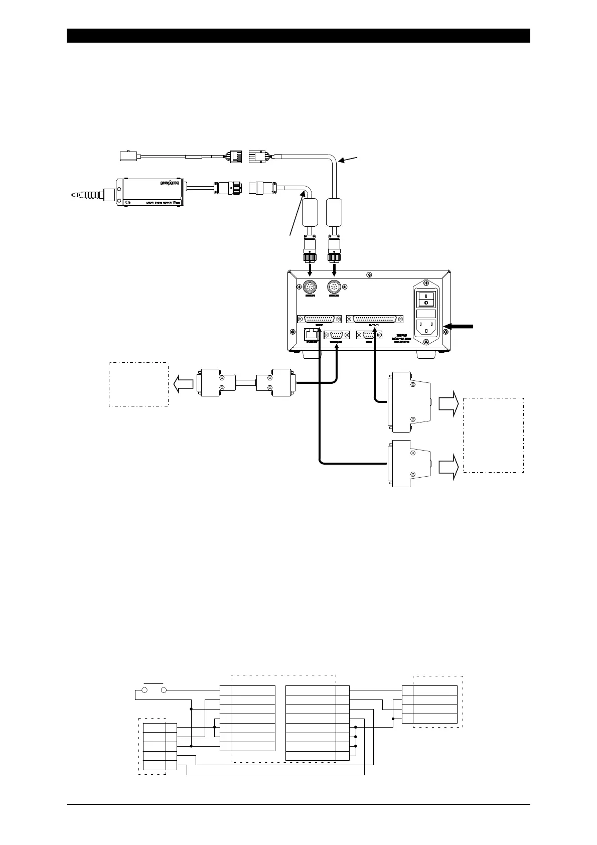
Example connection
E04SR200935A
E04SR200935A
* To connect the displacement sensor or the load cell to the welding head and the
follow-up mechanisms, refer to the documentation of the welding head and the
follow-up mechanisms or contact us.
* For adjustment of the displacement sensor or the load cell in the welding head or
follow-up mechanisms, refer to the documentation of the welding head and the
follow-up mechanisms or contact us.
Example wiring 1: Connecting both displacement sensor and load cell
Set Disp Measure Mode to SYNC(0).
WELD START1
18
17
COM
2NDST-DISP1
10 LS1
14
22 EXT.COM
23
24
25
EXT.COM
EXT.24V
INCOM
1
2
3
4
5
+24V
LS
COM
SV+
SV-
13
Foot Switch
ZH
INPUT
ISB-800A
STOP
COM
13
15
WE1 STOP
INPUT
MU-100A(SYNC mode)
8
OUTCOM
27
28
34
35
36OUTCOM
37
SV11
15
LEV-DISP11
OUTCOM
OUTCOM
SVCOM
OUTPUT
Welding
machine
Welding
head
Se
uence
PC
Sequencer
Load cell extension cable (option)
Power cable
(option)
Load cell (option)
Displacement sensor (option)
Output connector
(attached)
Input connector
(attached)
Displacement sensor
conversion adapter (option)
RS-232C harness
(option)
 Loading...