MU-100A
10. Setting of Measurement Mode and Schedule
10-6
(4) Sample Hold 2 Mode “Disp Measure Mode : SH2(3)”
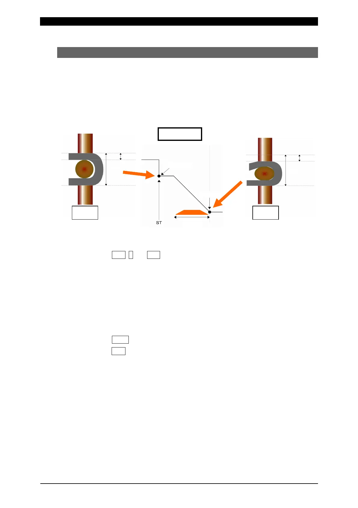
This is the mode for measuring displacement. The displacement from “ST-DISP1” or
“ST-DISP2” (second axis) input to the end of welding can be measured and judged.
(The displacement can be checked at a given point in time.)
This is used for stopping welding at the set displacement after internally resetting
displacement to zero before welding.
a. Setting of measurement mode
1
Press FUN, 0 and ENT keys in this order to select “0=Setup”.
2Select the setting object between “Axis1(0)” (first axis) and “Axis2(1)” (second
axis).
3Set No.3 “Disp Measure Mode” (measurement mode of displacement sensor) to
“SH2(3)” (sample hold 2 mode).
4When not using the load cell, set No.8 “Force Measure Mode” (measurement
mode of load cell) to “OFF(4)” (load cell off mode).
b. Setting of measurement schedule
1
Press MONI key to display the normal screen.
2Press SCH key to select “SCH Axis”.
3Select the setting object between “Axis1(0)” (first axis) and “Axis2(1)” (second
axis) to set the schedule number.
4Set the monitoring level according to your use conditions.
Monitoring of the after-welding workpiece thickness
No.6 “After Weld Work LO” (after-welding workpiece thickness lower limit)
No.7 “After Weld Work UP” (after-welding workpiece thickness upper limit)
5Set the level output according to your use conditions.
Displacement level output
No.14 “Displacement Level1”
No.15 “Displacement Level2”
No.16 “Displacement Level3”
±0.00 mm
WELD
value
Internal
zero
reset
WELD value
WORK
value
Internal
zero reset
Before
welding
After
welding
WELD
value
Weld time
 Loading...