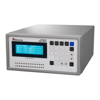
MU-100A
6. Interface
6-5
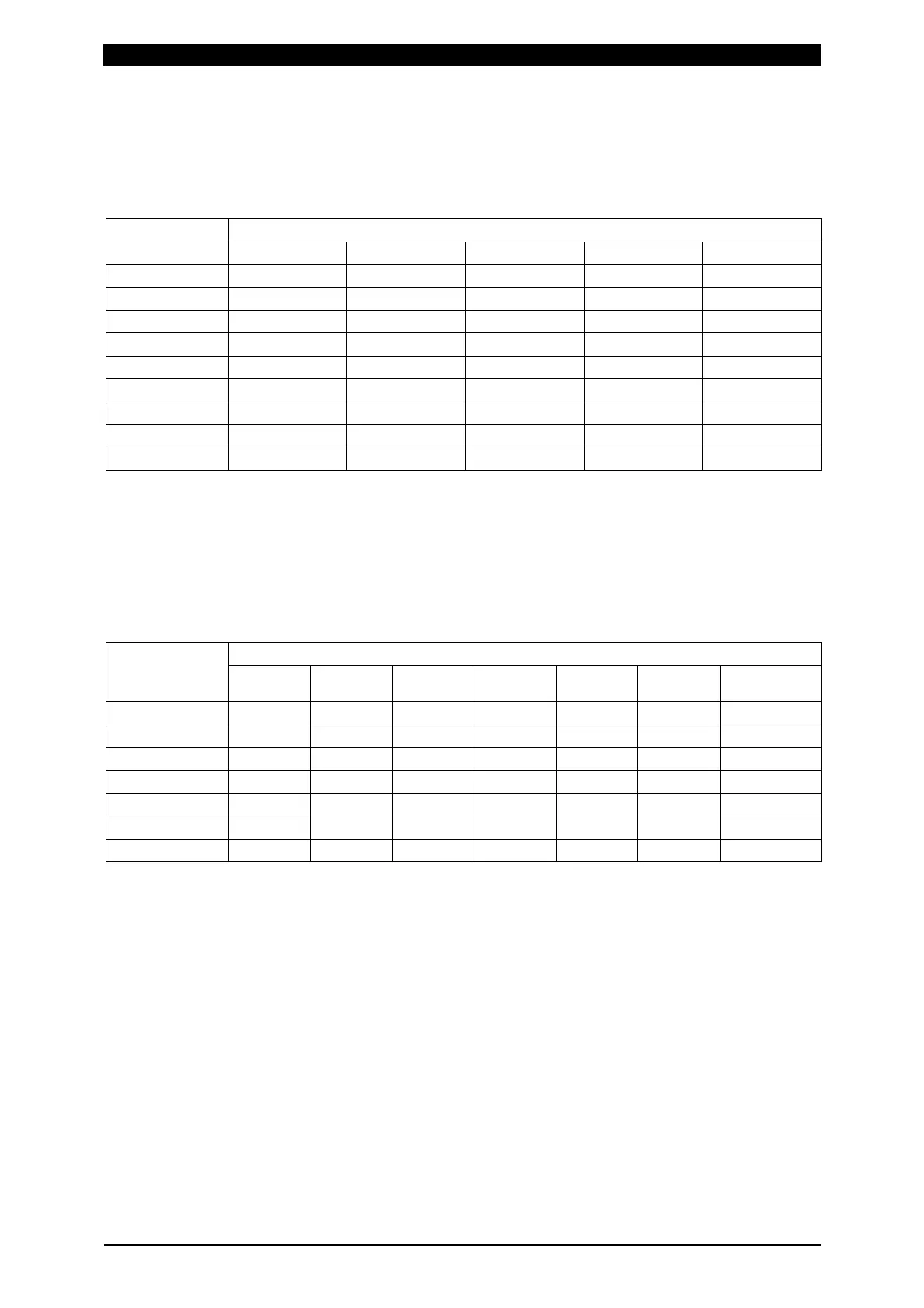
*1 Output value of V-SIG11 and V-SIG21
According to the range set in “Disp Voltage Range” (see 8. Function Setting), the present value of the
displacement sensor is converted to ±10 V to be output (see table below). When the present value of
displacement sensor exceeds the set range, the value is saturated with ±10 V.
Output voltage
Disp Voltage
Range setting
+10 V +5 V 0 V -5 V -10 V
0.255 +0.255 mm +0.127 mm 0 mm -0.127 mm -0.255 mm
0.511 +0.511 mm +0.255 mm 0 mm -0.255 mm -0.511 mm
1.023 +1.023 mm +0.511 mm 0 mm -0.511 mm -1.023 mm
2.047 +2.047 mm +1.023 mm 0 mm -1.023 mm -2.047 mm
4.095 +4.095 mm +2.047 mm 0 mm -2.047 mm -4.095 mm
8.191 +8.191 mm +4.095 mm 0 mm -4.095 mm -8.191 mm
16.383 +16.383 mm +8.191 mm 0 mm -8.191 mm -16.383 mm
32.767 +32.767 mm +16.38 mm 0 mm -16.38 mm -32.767 mm
65.535 +65.535 mm +32.76 mm 0 mm -32.76 mm -65.535 mm
When monitoring the waveform with an oscilloscope, use an oscilloscope whose channels are
insulated.
*2 Output value of V-SIG12 and V-SIG22
Based on the rated capacity set in “L.C. Rated Capacity” (see 8. Function Setting), the load variation
is converted to 0 to +10 V to be output (see table below). When the present value of the load cell
exceeds the set rated capacity, the value is saturated with 10 V.
Output voltage
Load cell
0 V +2 V +4 V +6 V +8 V +10 V
L.C. Rated
Capacity
LS-20NC 0 N 4 N 8 N 12 N 16 N 20 N 20 N
LS-50NC 0 N 10 N 20 N 30 N 40 N 50 N 50 N
LS-200NC 0 N 40 N 80 N 120 N 160 N 200 N 200 N
LS-500NC 0 N 100 N 200 N 300 N 400 N 500 N 500 N
LS-2000NC 0 N 400 N 800 N 1200 N 1600 N 2000 N 2000 N
LS-5000NC 0 N 1000 N 2000 N 3000 N 4000 N 5000 N 5000 N
LCN-A-10KN 0 N 2000 N 4000 N 6000 N 8000 N 10000 N 10000 N
When monitoring the waveform with an oscilloscope, use an oscilloscope whose channels are
insulated.


 To Next Page