APPENDIX F: RELAY TIMING DIAGRAMS
UB25 LINEAR DC RESISTANCE WELDING CONTROL
990-665 F-3
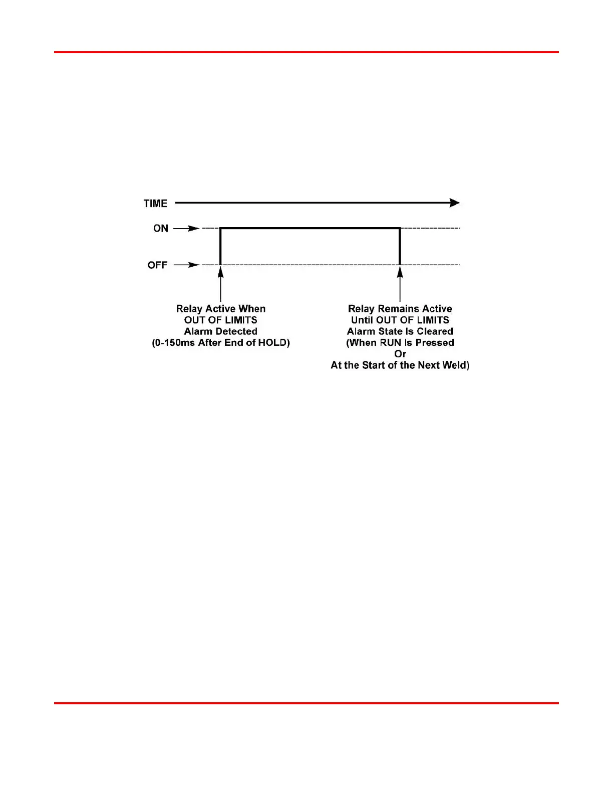
OUT OF LIMITS
• P1 HIGH LIMIT
• P1 LOW LIMIT
• P2 HIGH LIMIT
• P2 LOW LIMIT
The relay will switch when the Control senses any OUT OF LIMITS condition. It will start 0 - 150
milliseconds after the end of HOLD and will stay energized until the OUT OF LIMITS alarm state is
cleared by pressing the RUN button, or at the start of the next weld.
• P1 HIGH LIMIT. The relay signal will switch when the Control senses that the Pulse 1 energy
is higher than the programmed upper limit. It will start 0 - 150 milliseconds after the end of
HOLD and will stay energized until the OUT OF LIMITS alarm state is cleared by pressing the
RUN button, or at the start of the next weld.
• P1 LOW LIMIT. The relay signal will switch when the Control senses that the Pulse 1 energy
is lower than the programmed lower limit. It will start 0 - 150 milliseconds after the end of
HOLD and will stay energized until the OUT OF LIMITS alarm state is cleared by pressing the
RUN button, or at the start of the next weld.
• P2 HIGH LIMIT. The relay signal will switch when the Control senses that the Pulse 2 energy
is higher than the programmed upper limit. It will start 0 - 150 milliseconds after the end of
HOLD and will stay energized until the OUT OF LIMITS alarm state is cleared by pressing the
RUN button, or at the start of the next weld.
• P2 LOW LIMIT The relay signal will switch when the Control senses that the Pulse 2 energy is
lower than the programmed lower limit. It will start 0 - 150 milliseconds after the end of HOLD
and will stay energized until the OUT OF LIMITS alarm state is cleared by pressing the RUN
button, or at the start of the next weld.