CHAPTER 3: USING UB25 WELDING FUNCTIONS
UB25 LINEAR DC RESISTANCE WELDING CONTROL
990-665 3-11
Note: When using the energy limits monitor, always select a monitor mode that is different from the
feedback mode. For example:
• If you are welding in constant current, monitor voltage.
• If you are welding in constant voltage, monitor current.
• If you are welding in constant power, monitor current or voltage.
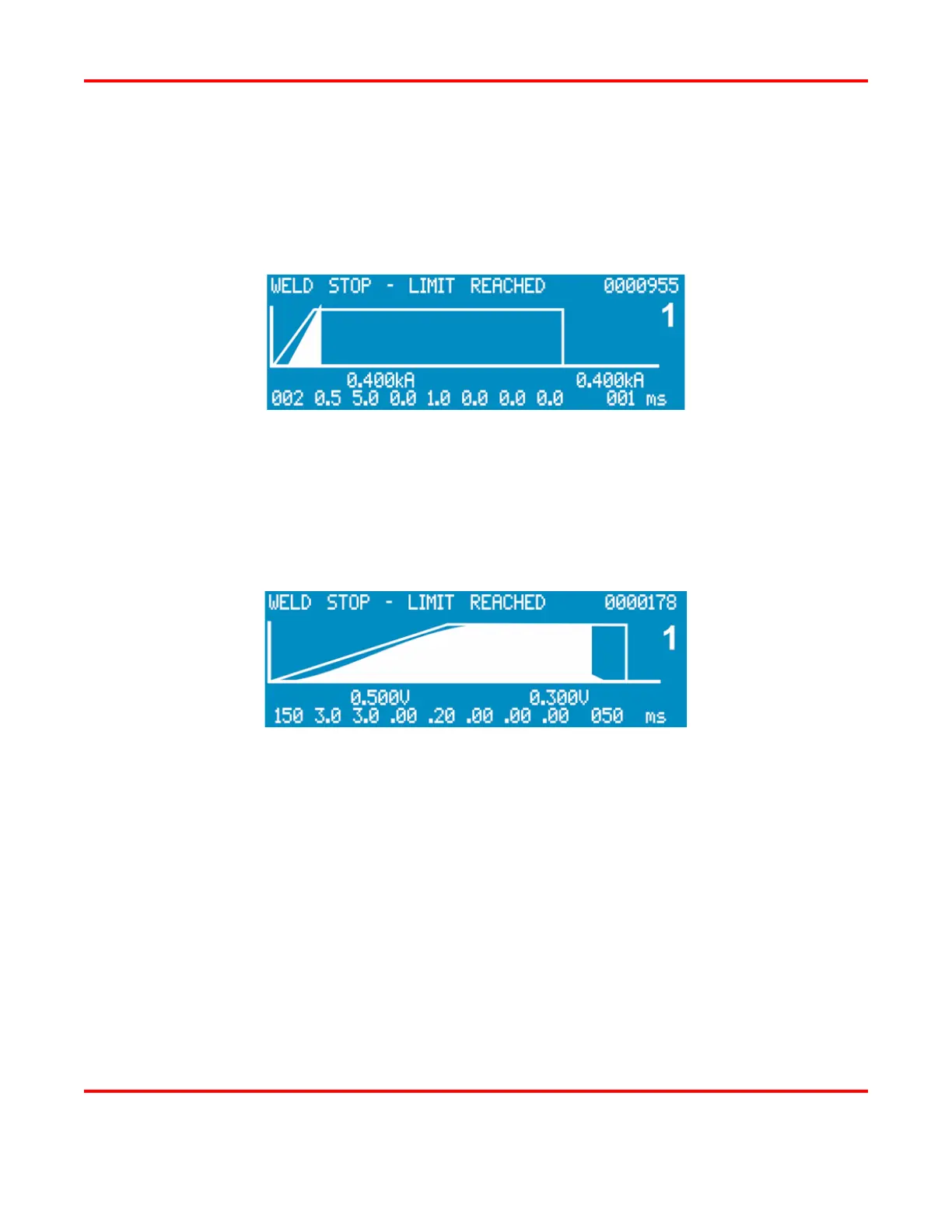
Example 1: Energy Limit Weld Termination
Example #1: In the profile above, the weld current is exceeding the selected upper limit before the
end of the welding cycle. The spike in the current waveform indicates that parts were misplaced. In
this case, the operator has selected the option to terminate the weld energy under this condition, so
the energy limits monitor terminates the Pulse 1 weld and inhibits the Pulse 2 weld if it had been
programmed.
Example 2: Sufficient Current Level
Example #2: In the profile above, the weld current limit is at a sufficient level to get a good weld.