3-34 | Model 933S UV Analyzer
Figure 3-18.
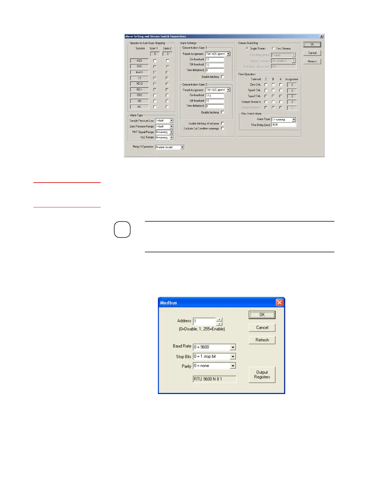
Modbus dialog box.
Figure 3-17.
Alarm Setting and
Stream Switch
Parameters dialog
box.
j. Optional Serial Communication for Modbus:
If using the Modbus/Customer Data Acquisition port, view the
Modbus dialog box and configure parameters to enable the Mod-
bus port.
If you need to alter the settings, refer to “Modbus Settings” in Chap-
ter 4 before making changes. For more information about Modbus
implementation on the analyzer, contact AMETEK.
After configuring the Modbus Port parameters, click OK then Ap-
ply. Save the changes to EEPROM.
NOTE
Setup (tab)
Modbus Settings
 Loading...


