2
3
15
13
16
20
19
21
14
10
374037
17
18
22
12
6
11
4
7
5
8
21
20
24
23
9
19
25
1
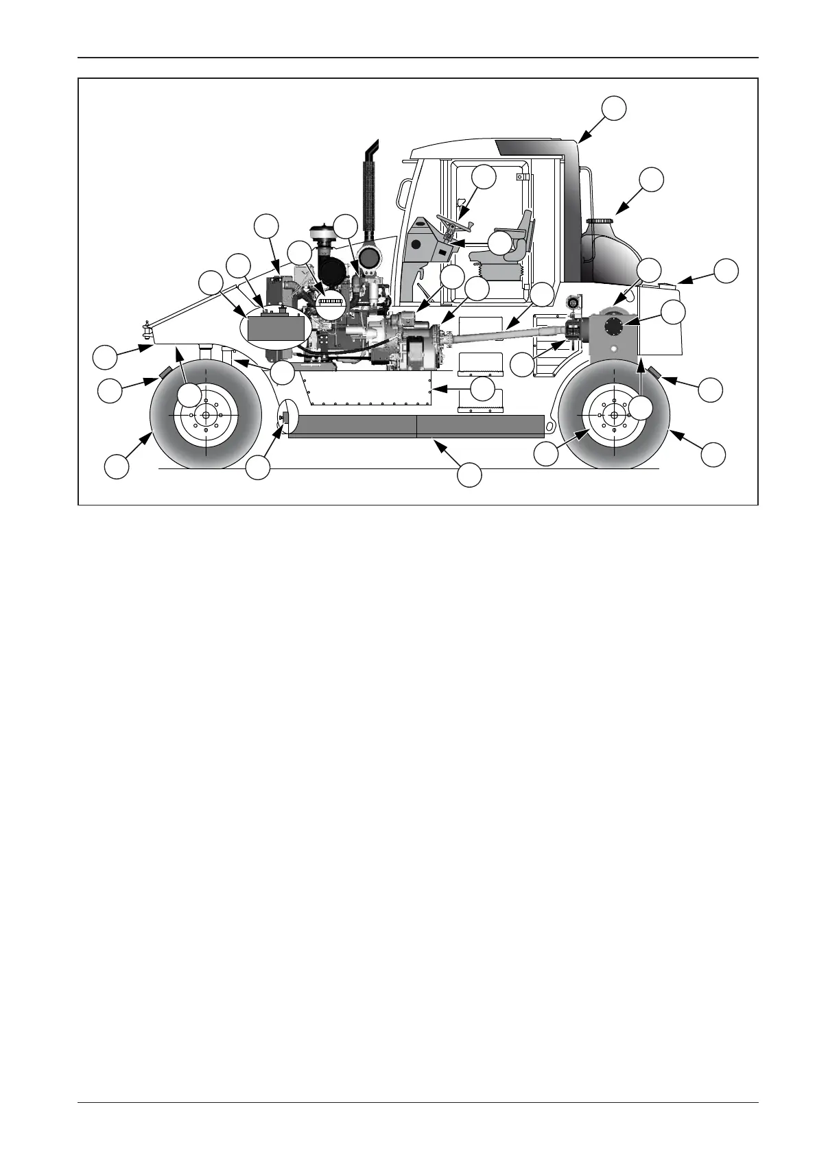
2.5. Machine Description
AP 240 Pneumatic Roller- Machine’s individual parts
1 - Roller Frame
2 - Engine
3 - Engine Radiator + Hydraulic Circuit Cooler + Gearbox
Cooler
4 - Gearbox incl. Torque Converter
5 - Final Drive Housing incl. Dierential
6 - Final Transmissions
7 - Propeller Shaft
8 - Parking and Emergency Brake
9 - Driving Brakes (rear wheels only)
10 - Front Axle incl. Telescopic Cylinders
11 - Pump for Compressor Drive
12 - Power Assisted Steering
13 - Battery (cylinder’s LH side)
14 - Hydraulic Tank (cylinder’s RH side)
15 - Additional Water Weight Closure*
16 - Fuel Tank
17 - Driver’s Control Stand
18 - Sprinkling Tank
19 - Tire Sprinkling
20 - Wheels
21 - Scrapers
22 - Protective ROPS Frame
23 - Additional Weight
24 - Ballast Space Lids
25 - Additional Water Weight Drain *
* - If waterproof frame for additional weight incl. water me-
dium is used with the Machine, then please refer to Speci-
cation Manual - “The Weights”.