Table of Figures Page No
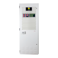
Figure 4-1 - EvacU
ELITE
and FireFinder
PLUS
24U COMBO unit - external view ................................... 6
Figure 4-2 - All-purpose back plane board ......................................................................................... 8
Figure 4-3 Front view of the universal rack ......................................................................................... 8
Figure 4-4 Side view of the universal rack .......................................................................................... 9
Figure 4-5 Power supply module...................................................................................................... 10
Figure 4-6 Primary power supply labelling ........................................................................................ 10
Figure 4-7 Secondary power supply labelling ................................................................................... 11
Figure 4-8 Power supply distribution board ...................................................................................... 12
Figure 4-9 Three power supply modules connected to the power supply distribution board .............. 13
Figure 4-10 Power supply - showing the primary power supply module ............................................ 13
Figure 4-11 Main GUI and LED membrane ...................................................................................... 14
Figure 4-12 Graphical user interface ................................................................................................ 15
Figure 4-13 Distribution CPU ........................................................................................................... 16
Figure 4-14 Multi-purpose output card ............................................................................................. 16
Figure 4-15 Multi-purpose interface card .......................................................................................... 17
Figure 4-16 Dual 25-watt amplifier ................................................................................................... 18
Figure 4-17 50-watt amplifier ........................................................................................................... 18
Figure 4-18 150-way amplifier .......................................................................................................... 19
Figure 4-19 Quad radial EIS line card .............................................................................................. 20
Figure 4-20 Dual loop EIS line card.................................................................................................. 20
Figure 4-21 Network interface card .................................................................................................. 21
Figure 4-22 Detail on fitting the SFP module to the NIC for VDSL Connection (2 core copper) ......... 22
Figure 5-1 Front Control Panel ......................................................................................................... 23
Figure 5-2 Front control panel with individual EWS controls and indicators highlighted ..................... 27
Figure 5-3 Emergency zone with indicators highlighted .................................................................... 27
Figure 5-4 Emergency zone with controls highlighted ....................................................................... 28
Figure 5-5 Front control panel with the individual EIS controls and indicators highlighted ................. 28
Figure 5-6 WIP handset with controls highlighted ............................................................................. 29
Figure 5-7 WIP handset with indicators highlighted .......................................................................... 29
Figure 5-8 LED Indicators ................................................................................................................ 30
Figure 6-1 Main menu screen .......................................................................................................... 42
Figure 6-2 Access level screen ........................................................................................................ 43
Figure 6-3 Distribution CPU card status screen ................................................................................ 45
Figure 6-4 Distribution CPU card status ........................................................................................... 46
Figure 6-5 Input status ..................................................................................................................... 46
Figure 6-6 Distribution CPU card status - showing the outputs ......................................................... 46
Figure 6-7 Network interface card status screen .............................................................................. 47
Figure 6-8 Network interface card status .......................................................................................... 47
Figure 6-9 Multi-purpose interface card status screen ...................................................................... 48
Figure 6-10 Multi-purpose interface card status................................................................................ 48
Figure 6-11 Multi-purpose interface card showing the outputs .......................................................... 49
Figure 6-12 Multi-purpose output card status screen ........................................................................ 49
Figu4re 6-13 Multi-purpose output card status ................................................................................. 50
Figure 6-14 Output status ................................................................................................................ 50
Figure 6-15 Quad radial EIS line card status screen ......................................................................... 51
Figure 6-16 Quad radial EIS line card status .................................................................................... 51
Figure 6-17 Handset status .............................................................................................................. 51
Figure 6-18 Quad radial EIS card status showing the inputs ............................................................. 52
Figure 6-19 Dual loop EIS line card status screen ............................................................................ 52
Figure 6-20 Dual loop EIS line card status ....................................................................................... 53
Figure 6-21 Handset status .............................................................................................................. 53
Figure 6-22 Dual loop EIS line card input status screen ................................................................... 53
Figure 6-23 Dual loop EIS line card output status screen ................................................................. 54
Figure 6-24 Dual 25-watt amplifier card status screen ...................................................................... 55
Figure 6-25 Dual 25-watt amplifier card status ................................................................................. 55
Figure 6-26 Amplifier status ............................................................................................................. 55
Figure 6-27 50-watt amplifier card status screen .............................................................................. 56
Figure 6-28 Graphical user interface status screen .......................................................................... 57
 Loading...