Figure 6-29 Graphical user interface status ...................................................................................... 57
Figure 6-30 Power supply status screen .......................................................................................... 58
Figure 6-31 Power supply status ...................................................................................................... 58
Figure 6-32 Power supply module status ......................................................................................... 58
Figure 6-33 Battery status ................................................................................................................ 59
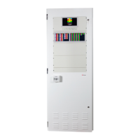
Figure 7-1 24U Cabinet – Front and side view ................................................................................. 73
Figure 7-2 24U Cabinet - Rear view showing mounting points .......................................................... 74
Figure 7-3 24U Cabinet – Top view showing the gland plate and cable entry.................................... 74
Figure 7-4 13U Cabinet - Front and side view .................................................................................. 75
Figure 7-5 13U Cabinet - Rear view showing mounting points .......................................................... 75
Figure 7-6 13U Cabinet - Top view showing gland plate and cable entry .......................................... 76
Figure 7-7 13U Cabinet showing the mains isolator, earth point and battery isolator ......................... 76
Figure 7-8 24U Cabinet showing the mains isolator, earth point and battery isolator ......................... 77
Figure 8-1 Label 3203 detailing terminations for each card type ....................................................... 79
Figure 8-2 MIC wiring - standard ...................................................................................................... 83
Figure 8-3 MIC wiring - voltage reversal ........................................................................................... 84
Figure 8-4 Dual 25Watt amplifier wiring............................................................................................ 89
Figure 8-5 50Watt amplifier wiring .................................................................................................... 92
Figure 8-6 50Watt amplifier wiring .................................................................................................... 94
Figure 8-7 Quad radial EIS wiring .................................................................................................... 97
Figure 8-8 Dual loop EIS wiring ..................................................................................................... 100
Figure 8-9 Network wiring - side by side cabinets ........................................................................... 103
Figure 8-10 Network wiring - 2 core copper .................................................................................... 104
Figure 8-11 Network wiring – Single mode, single fibre .................................................................. 105
Figure 8-12 Network wiring - Single mode, dual fibre ..................................................................... 106
Figure 8-13 Network wiring - Multi mode dual fibre ......................................................................... 107
Figure 8-14 Network wiring – Mixed - Fibre .................................................................................... 108
Figure 8-15 Networking wiring - Mixed - UTP ................................................................................. 109
Figure 8-16 Correct speaker wiring termination .............................................................................. 110
Figure 8-17 Incorrect speaker wiring termination ............................................................................ 111
Figure 8-18 Cable routing - left hand side ...................................................................................... 112
Figure 8-19 Cable routing - right hand side .................................................................................... 113