Section 6 Operating Principles
6-4
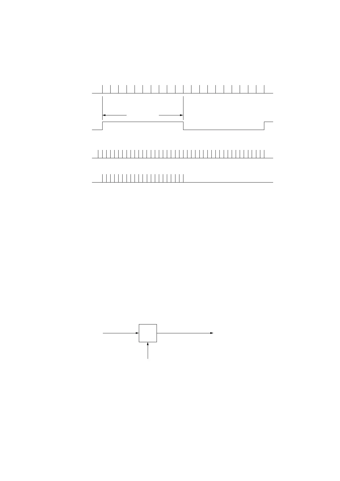
Pulse number to measure = N
Gate time T
Pulse number = M
Pulse to measure
N divisions of
pulse to measure
Internal count
clock
Count pulse
1· · · · · · · · · · · · · · · · · · · · · · · · · N
NNN11
2233······ ······
Fig. 6-3 Reciprocal Method
In the reciprocal method, the count error value will vary according to the size of the noise applied to the input signal
because the gate time is determined by the input signal. This is added as trigger error noted by measurement error. 6.4
“Trigger Error” describes count error due to trigger error. The final measurement accuracy is as follows:
Measurement accuracy = ±1 count ± time base accuracy × measurement frequency ± trigger error
After Input1 uses the heterodyne down converter method to convert the signal ™to measure to an IF signal, it displays the
count results using either the direct count method (when count mode is NORMAL) or the reciprocal method (when count
mode is FAST).
Connecting the signal to measure to the Input 1 connector mixes it with the local N harmonics in the harmonic mixer to
obtain the IF signal.
MIX
IF signal
(frequency Fx-N · F1)
N-ary harmonics signal
(frequency N · F1)
Measurement signal
(frequency Fx)
Fig. 6.4 Heterodyne Method
The IF signal is fed into the counter circuit after being amplified by the AMP, and it is then counted. If Fx is the frequency
of the signal to measure, F1 is the local frequency, and F2 is the frequency of the IF signal counted, we get the following
calculation :
Fx=N · F1±F2