4-25
4.3.9 Trigger and Gate End
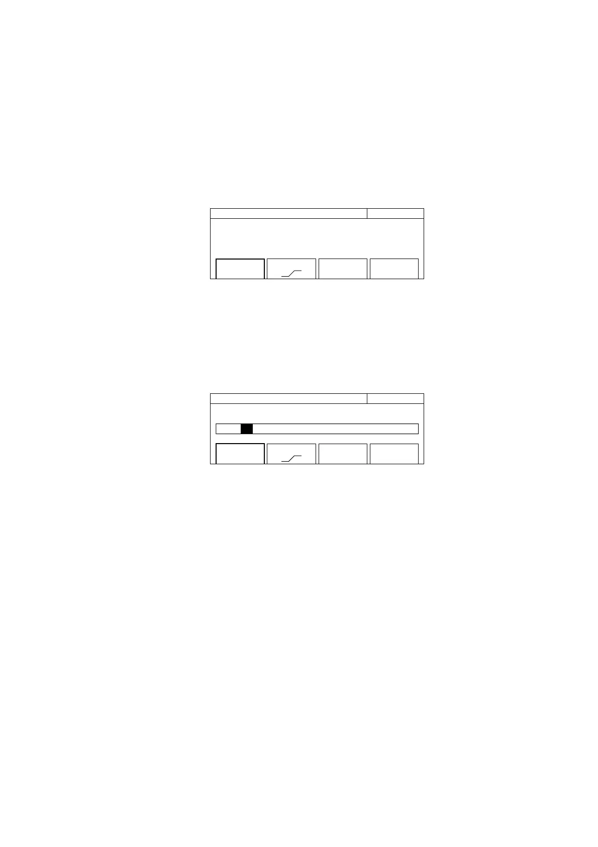
This function selects the trigger signal identifying the start of frequency measurement, select trigger polarity, and sets the
gate end. Pressing the [Trig] key displays the screen where you can set parameters (see Fig. 4-22).
20 000 000 0
00
Hz Trigger
Mode
[Int]
Slope
[ ]
Gate End
[On]
Fig. 4-22 Trigger Setup Screen
(1) Menu F1 : Selects whether to use one of the available triggers: internal trigger (Int), external trigger (Ext), or line
trigger (Line). Selecting menu F1 displays the trigger selection screen shown in Fig. 4.23.
Use the cursor keys to select either Int, Ext, or Line, and then press. Enter to return to the trigger setup screen shown
in Fig. 4-22. The parameter that you see is displayed within the square brackets [ ] of the F1 menu.
20 000 000 0
00
Hz Trigger
Mode [ Int / Ext / Line]
Mode
[Int]
Slope
[ ]
Gate End
[On]
Fig. 4-23 Trigger Selection Screen
(2) Menu F2 : Sets the polarity for detecting an external trigger signal and line trigger.
(3) Menu F4 : Sets whether or not (On/Off) to determine the end of carrier frequency measurement using gate width.
When gate end is On, the unit measures carrier frequency using the gate within the width set by the gate value. When
gate end if Off, the unit measures carrier frequency using the gate within a width until the burst wave goes off.
4.3 Parameters