Section 1 Outline
1-6
1.4 Specifications
1.4.1 Standard Specifications
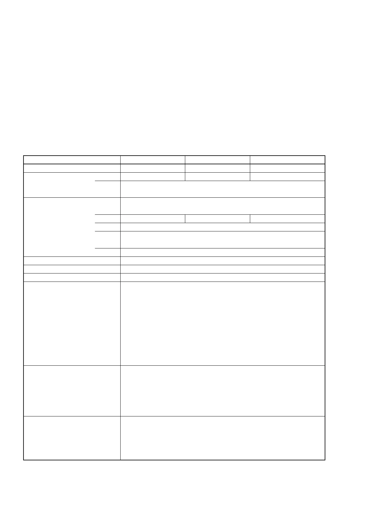
Table 1-6 shows MF2412B/MF2413B/MF2414B specifications.
Table 1-6 Standard Specifications
10 Hz to 40 GHz
600 MHz to 40 GHz
MF2414B
1
1.1
1.2
(1)
(2)
(3)
2
3
4
5
6
7
Frequency Range
CW Input1
Measurement Input2
Pulse-modulated wave measurement
Carrier frequency
Input1
Input2
Pulse width
Pulse repetition
External trigger pulse
Reference input
Reference output
Input level
Input/output impedance
Connection
Item
10 Hz to 20 G Hz
600 MHz to 20 GHz
10 MHz to 1 GHz (50 Ω)
10 Hz to 10 MHz (1 MΩ)
Cannot measure pulse-modulated wave
Pulse Width Narrow : 100 ns to 0.1 s
Wide : 1 us to 0.1 s
10 Hz to 4 MHz (Pulse off time : ≥240 ns )
≥1 us
1, 2, 5, 10 MHz
Internal reference signal (10 MHz) or External reference signal (1, 2, 5, or 10MHz)
Input1 (sine wave input) : –33 dBm to +10 dBm (<12.4 GHz)
: –28 dBm to +10 dBm (< 20 GHz)
: –25 dBm to +10 dBm (<26.5 GHz)
: {0.741×f (GHz) –44.6}dBm to +10 dBm (≤40 GHz)
Input2 (sine wave input) : 25 mVrms to 10 Vrms (1 MΩ)
25 mVrms to 2 Vrms (50 Ω)
External Trigger Input : 1.5 V
dc
± (2 to 10 V
p–p
)
Reference Input : 1 to 5 V
p–p
Reference Output : ≥2 V
p–p
(release terminal)
Input1 : 50 Ω
Input2 : 1 MΩ, ≤35 pF
50 Ω
External Trigger Input : ≥100 Ω
Reference Input : ≥1 kΩ
Reference Output : ≤400 Ω
Input1 : AC
Input2 : AC
External Trigger Input : DC
Reference Input : AC
Reference Output : AC
MF2412B
10 Hz to 27 GHz
600 MHz to 27 GHz
600 MHz to 40 GHz600 MHz to 20 GHz 600 MHz to 27 GHz
MF2413B