1-7
Table 1-6 Standard Specifications (Continued)
MF2414B
8
9
9.1
9.2
9.3
10
10.1
(1)
(2)
(3)
Input/output connectors
Gating function
Trigger
Trigger delay
Gate width
Pulse-modulated wave
measurement
Carrier frequency
measurement
Maximum resolution
Measurement time
Accuracy
Item
Input1 : N (MF2412B)
: SMA (MF2413B)
:K (MF2414B)
Input2 : BNC
External Trigger Input : BNC
Reference Input : BNC
Reference Output : BNC
Int : Detects trigger using measurement signal
Ext : Detects trigger using External Trigger Input
Line : Detects trigger using AC LINE
Time from trigger detection to count start : OFF, 20 ns to 0.1 s
≤320 ns can be changed in 20 ns increments
<1 us can be changed in 40 ns increments
≥1 us can be repeatedly changed by two significant digits
100 ns to 0.1 s (Pulse Width Narrow) <1 us can be changed in 20 ns increments
1 µs to 0.1 s (Pulse Width Wide)
≥1 µs can be repeatedly changed by two
significant digits
(Measurement in Manual measurement mode)
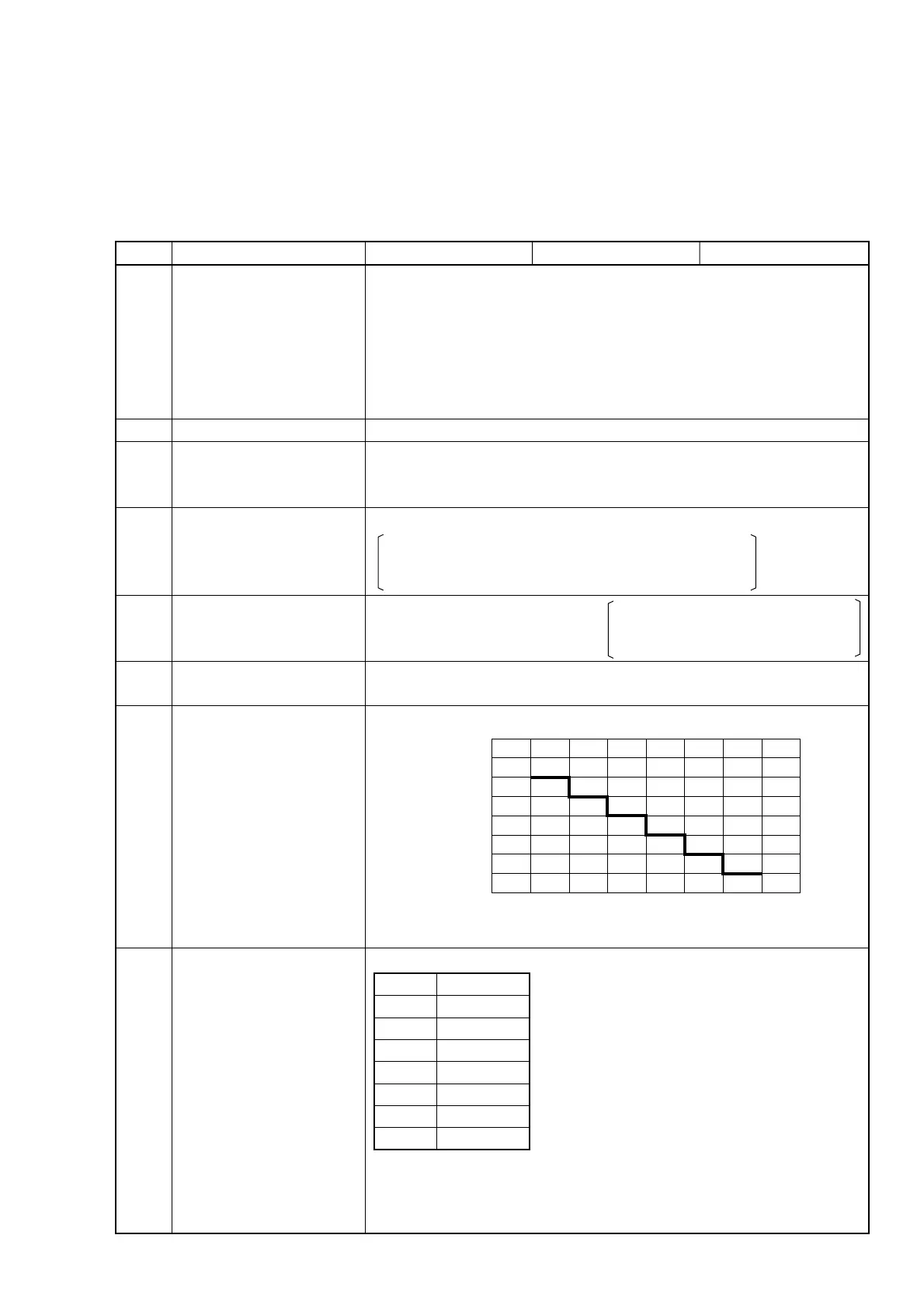
Resolution verses measurement time (measurement carrier frequency : 1 GHz)
± 1 count ± time base accuracy × measurement frequency ± trigger error
± Residual error 2 (measurement frequency (GHz)/2 count (rms)) ±1/T
GW
MF2412B MF2413B
Resolution Measurement Time
1 Hz 200 s
10 Hz 20 s
100 Hz 2 s
1 kHz 200 ms
10 kHz 20 ms
100 kHz 5 ms
1 MHz 5 ms
1 M
10 k
100
1
10 m
10 n 100 n 1 µ 10 µ 100 µ 1 m 10 m 100 m
Maximum resolution (Hz)
Pulse width (s)
measurement Time
T
MS = max (T,Ts)
× (1/(f
R×TGW) )
2
Test data
f
R : Resolution ……(see table)
T
GW : Gate width ……0.1/fR
Ts : Processing time ……50 us
T: Period ……2/f
R
1.4 Specifications