6-7
6.4 Trigger Error
When the count mode on INPUT1 is FAST and INPUT2 is the 1 MΩ system, this unit employs measurements using the
reciprocal method that calculates and displays frequency by making calculations from period measured value. When
performing period measurements, it takes the signal to measure as the gate time unlike the frepuency measurement, there-
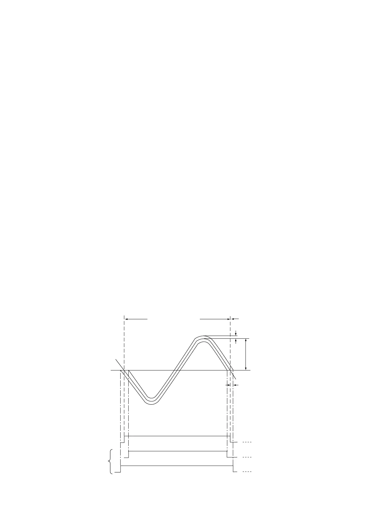
fore the error will be occured by minute noise components as fluctuation of the count time.
As shown in Fig. 6-6, when the gate is opened and closes due to a noise signal at the trigger point, the gate item lengthens
and shortens by only∆T.
If S is the gradient (V/sec.) of the ideal signal in the trigger level and E
N is the peak value of the noise signal, the following
relationship is established :
S= EN/∆T
This means that the maximum measurement period deviation due to noise is 2∆T, and if the measurement period is T, the
trigger error is expressed by the ratio of 2∆T and the measurement period T as follows :
2∆T/T = T2EN (peak value)/TS
For example, if period T and amplitude ES are sine waves, the gradient S of the trigger level is 2πES/T, resulting in the
following equation :
2∆T/T = EN (peak value)/πES (amplitude)
As shown in Fig. 6-6, an error of 2∆T occurs when there was trigger error for the ideal GATE. This is the counter error in
the reciprocal frequency measurement from section 6.2 and burst width measurement/burst period measurement from
section 6.3.
Measurement
period
T
E
N
E
S
∆T
Maximum period deviation=2∆T
GATE width : T
GATE width : T–2∆T
GATE width : T+2∆T
GATE with
trigger error
Ideal GATE
Fig. 6-6 Trigger Error Due to Noise
6.4 Trigger Error