Section 6 Operating Principles
6-6
6.3 Burst Width Measurement/Burst Period Measure-
ment
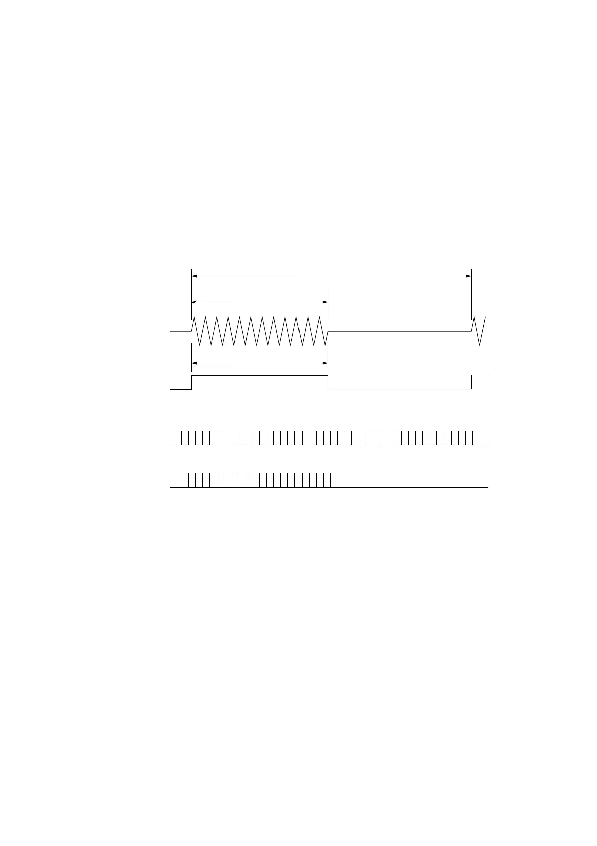
The signal to measure input from Input1 is detected by BURST DET and generates a pulse signal. This pulse signal is
taken as the gate time, and the clock number of the internal count clock is counted. For the pulse period, the time from the
start of a burst to the time of the start of the next burst (or the time from an end to the next end) is taken as the gate time, and
the same operation takes place.
Gate time T
Pulse number = M
Burst signal
to measure
N divisions of pulse
to measure
Internal count clock
Count pulse
Burst width
Burst period
1· · · · · · · · · · · · · · · · · · · · · · · · · N
Fig. 6-5 Burst Width Measurement
The gate is generated from the signal to measure, and the method for counting using the counting circuit is the same as that
for the reciprocal method. The error is also the same.
Note that error due to detection is newly added for burst width and period measurement. This will be ± 20 ns when using
this unit to measure a burst signal at an On/Off ratio of 40 dB and 0 cross (when On/Off is performed while the carrier
signal phase is 0 degrees). Consequently, measurement accuracy is as follows :
Measurement accuracy = ±20 ns ± time base accuracy × measurement pulse width ± trigger error
Burst signal to measure : On/Off ratio of 40 dB, 0 cross