4-23
4.3.8 Gating
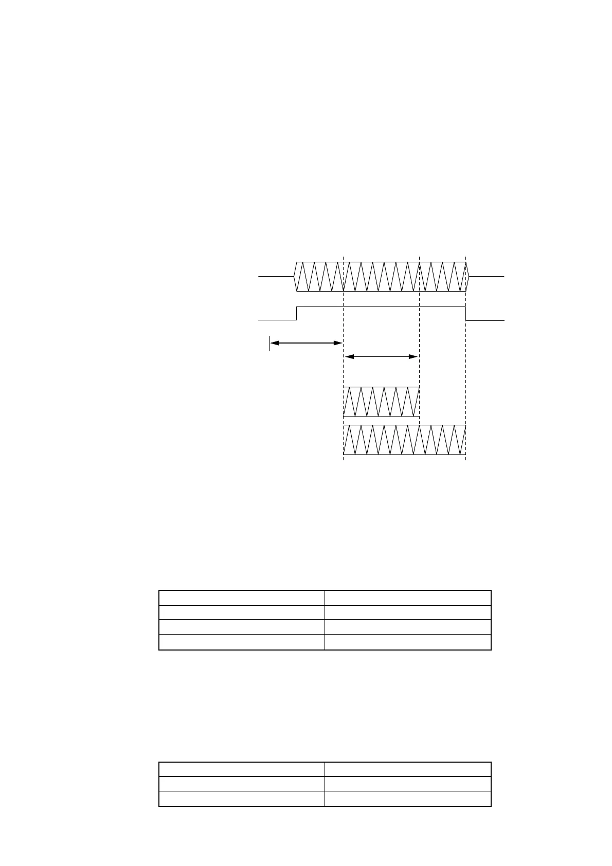
This function allows you to measure a frequency in any interval of the signal to measure. Based on the trigger signal, it
defines the interval for measuring the frequency according to the specified parameters such as a trigger delay, gate width,
and gate end. Note that the signal to measure at the prescribed level must exist in the measurement interval. Figure 4-20
shows the relationship between the parameters.
This function enables you to measure the frequency at a specific position of a burst signal.
Frequency measurement interval
Gate end : On
Gate end : Off
T
Measurement Signal
Trig Delay
Gate Width
Level of Measurement Signal
Trigger signal (standard)
Trigger delay
Gate width
Fig. 4-20 Gating Function Overview
The trigger delay width and gate width can be set while looking at the burst signal On/Off state shown on the screen.
The trigger delay width can be set between 0 ns and 100 ms. The setting resolutions are as follows:
Table 4-12 Trigger Delay Width Setting Resolutions
Trigger Delay Width
0 ns to 320 ns
320 ns to 1 us
1 us to 100 ms
Setting Resolution
20 ns
40 ns
Number of significant digits = 2
The gate width can be set between 100 ns and 100 ms. The setting resolutions are listed below.
When "Wide" is set as the burst width, the minimum value of the gate width becomes 1 us. If Wide is set as the burst width
and a value less than 1 us is set as the gate width, measurement will be performed at the gate width of 1 us.
Table 4-13 Gate Width Setting Resolutions
Gate Width
100 ns to 1 us
1 us to 100 ms
Setting Resolution
20 ns
Number of significant digits = 2
4.3 Parameters