4-45
4.4.7 Burst Wave Pulse Width and Repetition Period Measurement via Input1
When the Input1 connector and Burst mode are selected, the carrier frequency can be measured along with either the burst
signal pulse width or pulse repetition period.
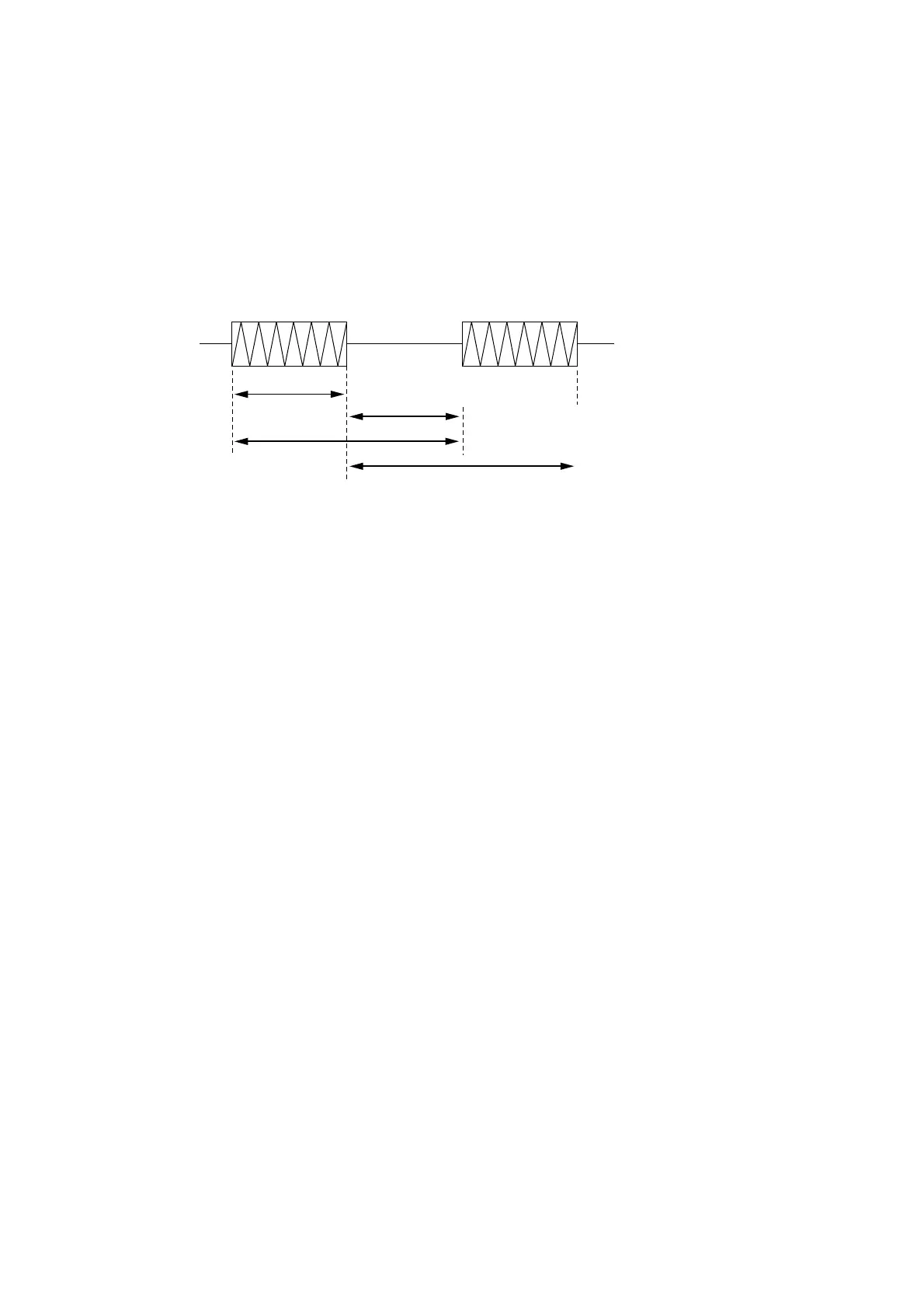
Pulse Width (Burst On)
Pulse Width (Burst Off)
Repetition Period (Rising Edge)
Repetition Period (Falling Edge)
Fig. 4-48 Burst Wave Measurement
(1) Connecting the input signal
Connect the signal to measure to the Input1 connector on the front panel.
Note:
Do not connect a signal of +10 dBm or higher to the Input1 connector.
(2) Setup
1) Press the [Preset] key to preset this unit.
2) Select the Burst mode.
Press the [Meas Mode] key. The Burst LED lights up.
3) Select the frequency acquisition mode.
To select the Manual mode, follow the procedure discussed in Section 4.4.2. Note that the Auto mode was
previously set at presetting.
4) Select the level acquisition mode.
To select the Manual mode, follow the procedure discussed in Section 4.4.3. Note that the Auto mode was
previously set at presetting.
4.4 Measuring