Section 4 Unit Operation
4-4
4.2 Screen Description
This unit has three major screens: a measurement screen, a setup screen, and a system screen. The measurement screen
further consists of two screens: a normal measurement screen and a template screen. The setup screen further consists of a
menu screen and a burst monitor screen.
This section provides a basic description of screen display.
Table 4-2 Screen Configuration
Major Classification
Measurement screen
Setup screen
System screen
Normal measurement screen
Template screen
Menu screen
Burst monitor screen
Minor Classification
4.2.1 Measurement Screen
Once you turn on power, the unit performs a self-check, and if it finds nothing wrong, it enters the measurement state and
displays the measurement screen. This unit has two kinds of measurement screens: the normal measurement screen and the
template screen.
[Normal Measurement Screen]
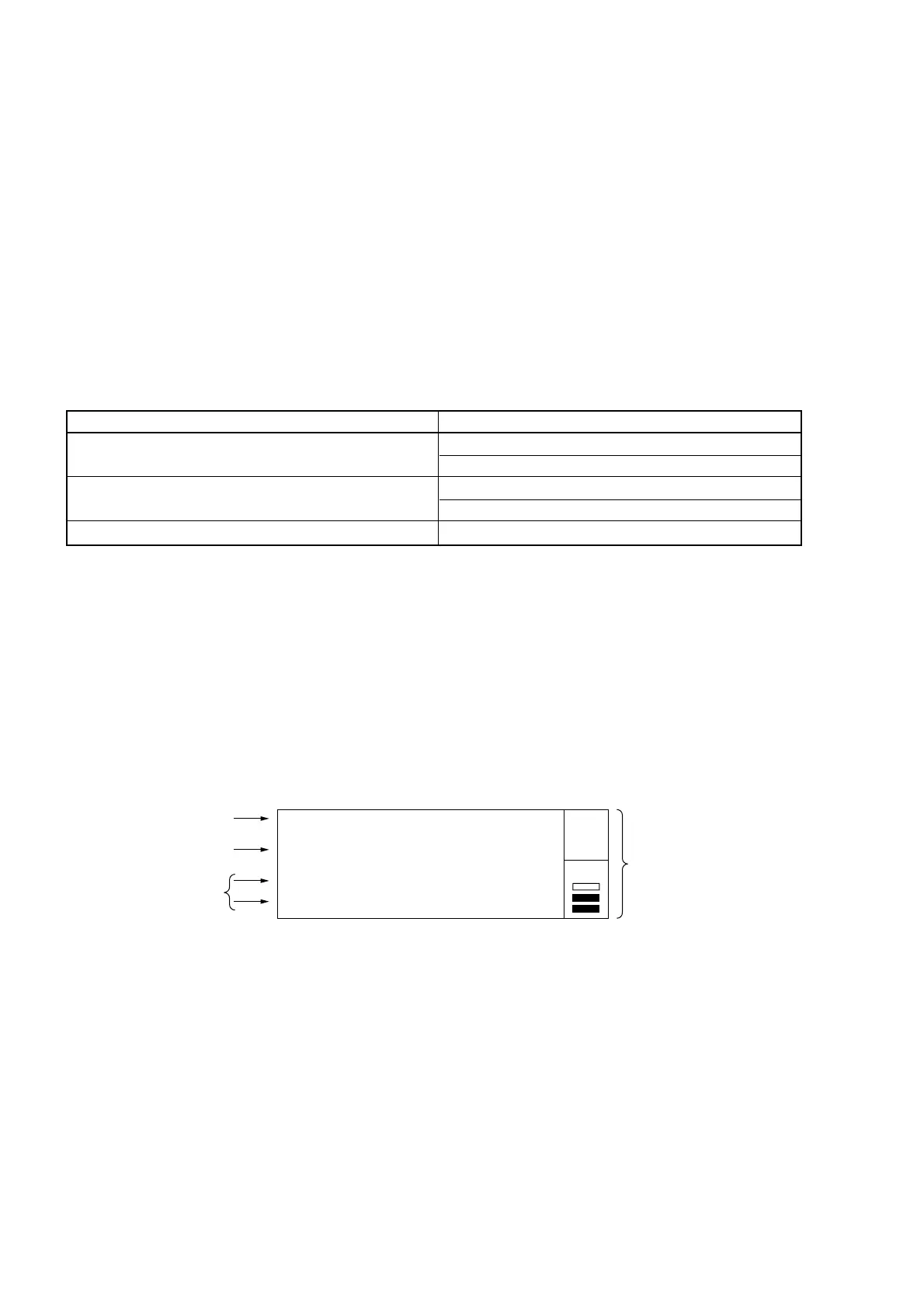
Figure 4-2 shows the normal measurement screen that displays frequency measurement results with numeric values. This
screen is displayed when the initial setup has been done.
(1) Main display
(2) Unit display
(3) Sub-display
20 000 000 000. 0
GHz MHz kHz Hz
(4) State display
Auto
Gate •
Max
Min
: 20 000 000 000.0 Hz
: 19 999 999 999.0 Hz
Fig. 4-2 Normal Measurement Screen
The following describes items (1) to (4) in Fig. 4-2.
(1) Main display
Displays frequency measurement results.
(2) Unit display
Displays units for frequencies displayed on the main display.
(3) Sub-display
Display changes depending on what function is specified such as statistical processing result, offset frequency
value, pulse width during burst measurement, or continuous period.
(4) State display
Displays the unit’s measurement state. Table 4-3 lists the measurement states and provides an overview.