Section 4 Unit Operation
4-12
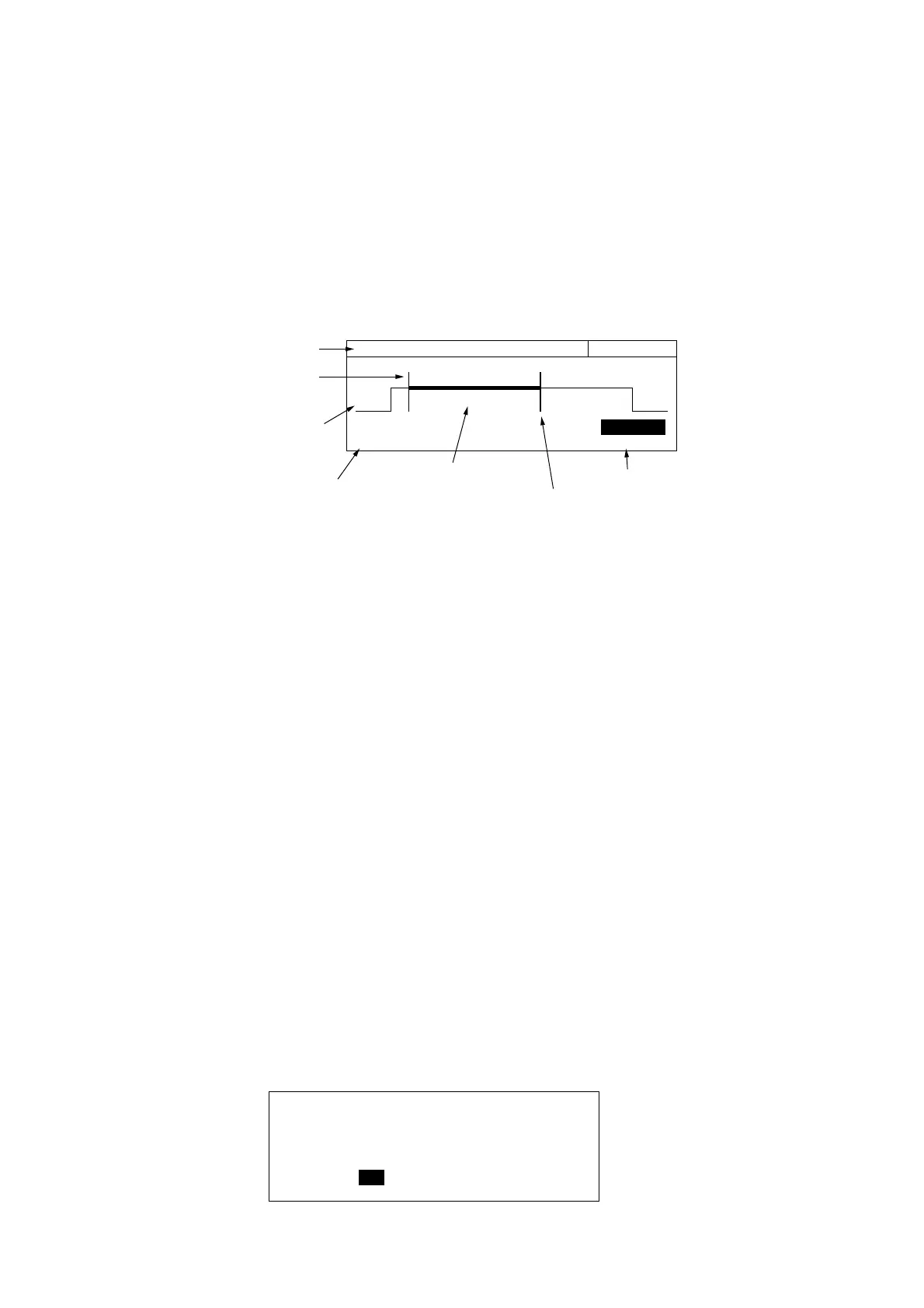
[Burst Monitor Screen]
This is the screen where you set trigger delay values and gate widths.
Pressing [TD] or [GW] displays the burst monitor screen shown in Fig. 4-7 below. You can set values while monitoring the
detection signal for individual burst signals that are input.
(1) Carrier frequency
(4) Trigger delay value
(7) Gate width value
(6) Gate width cursor
(5) Gate
(3) Inter detection signal
(2) Trigger delay cursor
20 000 000 0
00
Hz Gate Width
Trig Delay Gate Width
100.000 us 120.000 us
Fig. 4-7 Burst Monitor Screen
(1) Carrier frequency
Displays the carrier frequency measured by the currently selected gate.
(2) Trigger delay cursor
Shows the position of the trigger delay. It moves right and left accordingto the trigger delay value.
(3) Internal detection signal
Displays the burst detection signal.
(4) Trigger delay value
Displays the trigger delay value.
(5) Gate
Displays the count gate using a thick line. It moves right and left according to the trigger delay value and gate width
value.
(6) Gate width cursor
Indicates the gate width. Moves to the right and left according to the gate width value.
(7) Gate width value
Displays the value of the gate width.
You can set a highlighted parameter. Use the cursor keys [<] [>] or numeric keypad to make your settings.
4.2.3 System Screens
Fig. 4-8 shows the system screen that displays self-check results.
Anritsu MF2414B
---- Self-Check ----
RAM : Pass LCD-C : Pass
GPIB-C : Pass ASIC : Pass
DC : Pass PLL Lock : Pass
Freq Meas : Fail
Fig. 4-8 System Screen