6-3
6.2 Frequency Measurement
6.2 Frequency Measurement
Frequency means the number of vibrations per unit of time. Operating principle, which is called the most basic direct
counting of frequency measurement opens a gate between a precise unit of time created by a time base generation circuit,
passes through the signal to be measured, counts it using a counting circuit, and then displays the result.
The 50 Ω system (measurement frequency of 10 MHz to 1 GHz) on Input2 of this unit uses a direct count method.
Connecting the signal to be measured to the Input2 connector passes a 50 Ω/1 MΩ input impedance switch and adds the
AMP and SCHMITT circuits. To prevent miscounts due to noise, the AMP amplitude is controlled so that the input level
of the SCHMITT circuit remains constant regardless of the size of the input level.
The SCHMITT circuit converts the wave form of the amplified signal to a pulse and then sends it to the counting circuit.
The counting circuit uses the time base generator as the standard, opens the gate only as long as the gate time of the count
signal time (1 sec at a resolution of 1 Hz and 1 msec at a resolution of 1 kHz) for obtaining the necessary resolution, and
then counts the number of pulses. This pulse number is sent to the CPU which displays it as a measurement frequency.
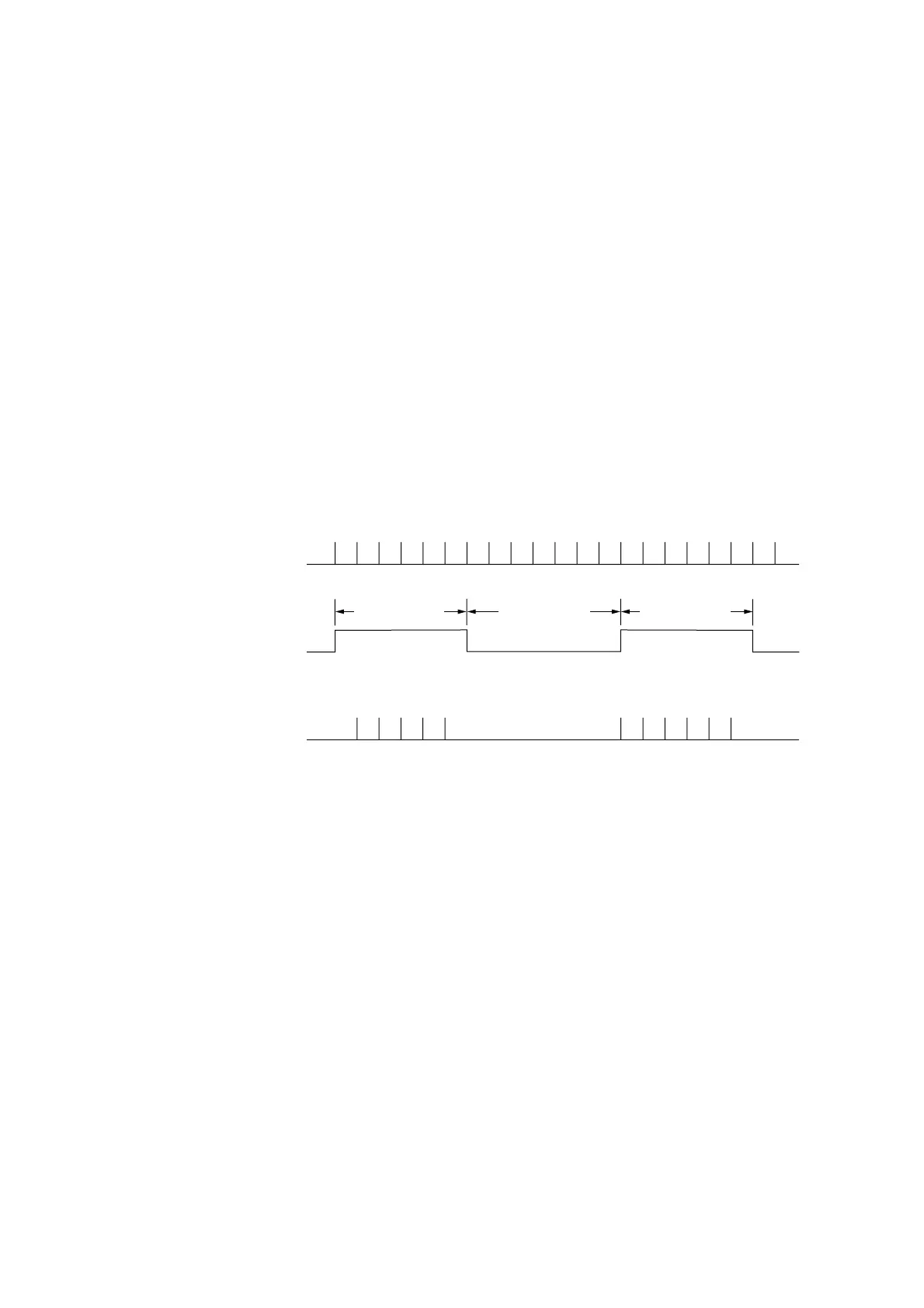
Gate time T1 Rest timeT2 Gate time T1
Pulse number = 5 Pulse number = 6
Pulse to measure
Gate
Count pulse
Fig. 6-2 Direct Counting
The pulse that is input has a ±1 count error for the number of pulses due to the gate and unsynchronized signal. This error
is the ±1 count item noted in the measurement error. Consequently, the final measurement accuracy is as follows :
Measurement accuracy =±1 count ± time base accuracy × measurement frequency
The 1 MΩ system (measurement frequency of 10 Hz to 10 MHz) on Input2 employs a reciprocal method. The signal to
measure, which was converted into a pulse wave form, is divided between 1/2 to 1/10
9
by the counting circuit. This
division rate is decided by calculating the optimum value on the CPU from the correspondence between the necessary
frequency resolution and the frequency of the signal to measure.
The counting circuit opens the gate for the amount of time required to divide the signal to measure only by the division rate,
measures the gate time, and then uses the CPU to calculate the frequency of the signal to measure from this gate time and
the division rate.