Section3 Panel Arrangement and Operation Overview
3-2
3.1 Panel Arrangement
This section describes the keys, switches, LED, connectors, and displays on the front, side, and back panels of MF2412B/
MF2413B/MF2414B.
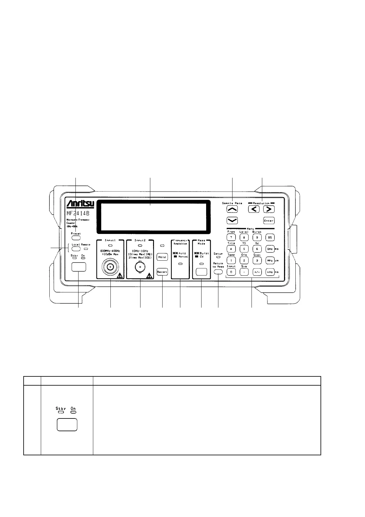
3.1.1 Front Panel
Fig. 3-1 shows the front panel and Table 3-1 describes its function.
13 11 10 9
1 2 3 4 5 6 7 8
12
Fig. 3-1 Diagram of Front Panel
Table 3-1 Function of Front Panel Components
No
1
Label
Power Switch, Stby LED and On LED
Switching the Power Line switch on the rear panel from Off to On puts this unit on
standby and supplies power only to the internal crystal oscillator. The green Stby
LED lights when the unit enters the standby state.
When the unit is in the standby state, pressing the Power switch turns on the unit and
supplies power to all circuits, allowing you to use the unit. The On LED lights when
the unit becomes ready.
When the unit is on, pressing the Power switch again puts the unit on standby.
Description