3-3
3.1 Panel Arrangement
Table 3-1 Function of Front Panel Components (Continued)
No
2
3
4
5
6
Label
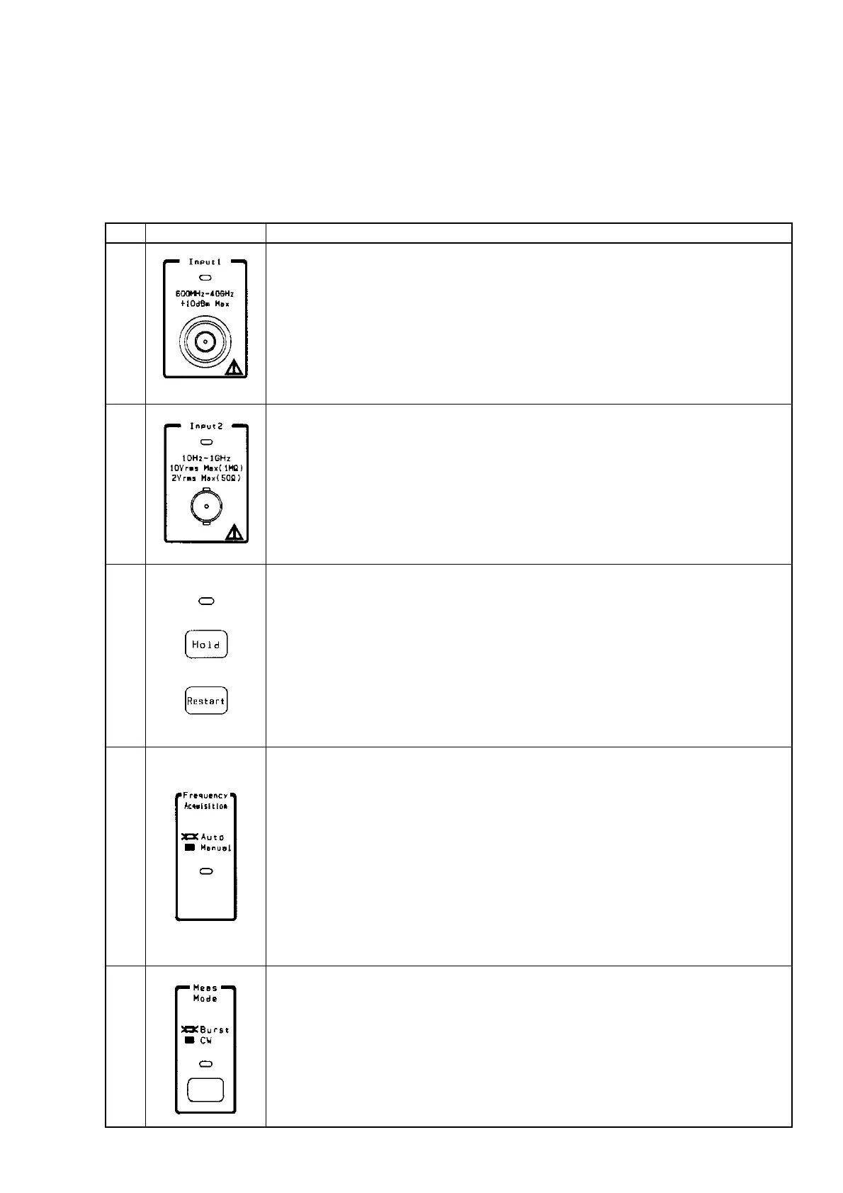
Input1 connector and Input1 LED
Connect the signal to this connector when measuring frequencies of 600 MHz or high-
er, particularly frequencies of 1 GHz or higher.
The maximum frequency and connector shape differ between models. The
MF2412B/MF2413B/MF2414B has an N/SMA/K connector with a maximum input
frequency of 20 GHz/27 GHz/40 GHz. The Input1 LED lights when the Input1 con-
nector becomes usable. To use the Input1 connector, select "Input1" from the Input
CH menu on the Input parameter setup screen.
Input2 connector and Input2 LED
Connect the signal to this connector when measuring frequencies of 10 MHz to 1 GHz.
The Input2 LED lights when the Input2 connector becomes usable. To use the Input2
connector, select "Input2" from the Input CH menu on the Input parameter setup
screen.
[Hold] key, [Restart] key, and Hold LED
While frequency measurement is being repeated, pressing the [Hold] key stops
measurement and continues to display the current value. This state is called a hold
state. While the unit is in the hold state, pressing the [Hold] key restarts measurement.
The Hold LED lights when the unit enters the hold state.
Pressing the [Restart] key restarts a measurement or statistical process.
While the unit is in the hold state, pressing the [Restart] key performs a measurement
or statistical process only once and places the unit in the hold state again (single
measurement).
Frequency Acquisition LED
This LED indicates whether the frequency of the signal input to the Input1 connector is
to be acquired automatically (Auto) or manually (Manual).
When "Auto" is selected, the unit will measure the input signal across the entire
measurement frequency band and then measure only the signal frequencies that have
reached the prescribed level.
When "Manual" is selected and a signal within the prescribed frequency input
tolerance is input, the unit will measure the frequency of that signal.
The Frequency Acquisition LED lights when "Auto" is selected as the frequency
acquisition mode. To select automatic frequency acquisition, select "Auto" from the
Mode menu on the Freq Acq parameter setup screen.
[Meas Mode] key and Meas Mode LED
This key is used to determine whether to measure burst waves (Burst) or continuous
waves (CW).
When burst wave measurement is selected, the unit can measure the carrier frequency,
burst signal width, and burst repetition period.
When continuous wave measurement is selected, the unit will measure that frequency.
The Meas Mode LED lights when burst wave measurement is selected.
Description