3-9
3.2 Operation Overview
3.2.2 Parameter Setup Hierarchy
Pressing the direct key to set parameters displays the corresponding setup screen. In the setup screen, you can set param-
eters listed in the first level column.
When there are more parameters than can be shown in level one, level two parameters will be displayed in the setup screen,
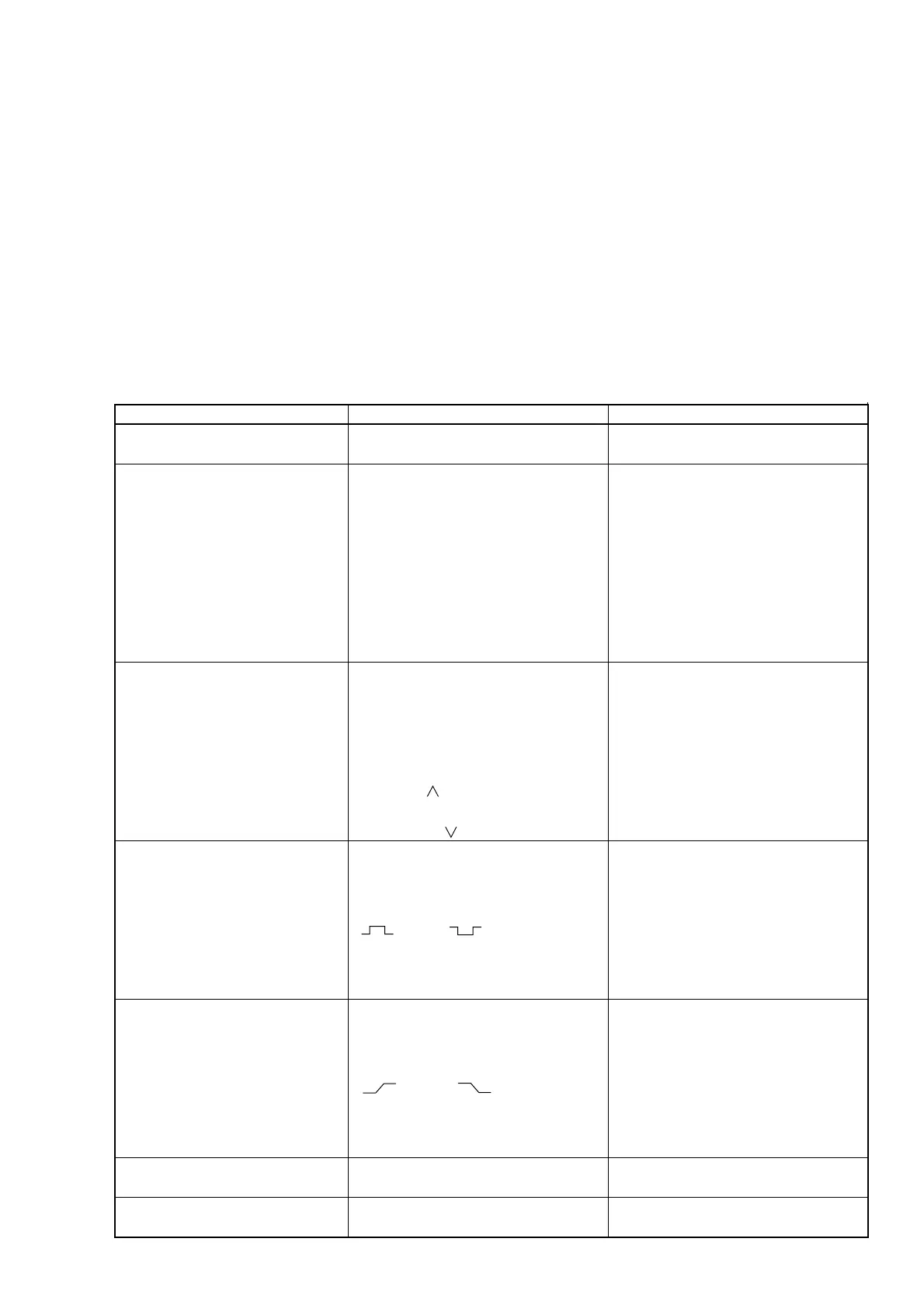
and you can set the various parameters there. Table 3-4 shows the hierarchical structure of the setup screen.
Table 3-4 Hierarchical Structure of Setup Screen
Direct Key
Measurement mode [Meas Mode]
CW/Burst
Frequency acquisition [Freq]
Level acquisition [Level]
Burst [Burst]
Trigger and gate End [Trig]
Trigger delay [TD]
Gate width [GW]
Level 1
None
Mode [Mode]
Auto/Manual
Measurement result assignment
[Last Measure]
Frequency value input [Set Freq]
Count method [Count]
Fast/Normal
Mode [Mode]
Auto/Manual
Auto setup value assignment
[Last Measure]
Level Up [ ]
Level Down [ ]
Burst measurement mode [Mode]
Freq/Width/Period
Bust measurement polarity [Polarity]
(Pos) / (Neg)
Burst width [Width]
Wide/Narrow
Trigger mode [Mode]
Int/Ext/Line
Trigger polarity [Slope]
(Rise) / (Fall)
Gate End [Gate End]
On/Off
Trigger delay value input
Burst monitor screen
Gate width value input
Burst monitor screen
Level 2
None
None
None
None
None
None
None