Section 4 Unit Operation
4-6
Table 4-5 Level Display Description
Display
Indicates that the input level is excessive.
Proper measurement cannot be made until the input level is lowered.
Indicates a perfect input level.
Indicates that the input level is measurable.
Indicates that the input level is too low.
Proper measurement cannot be made until the input level is raised.
Description
Over
to
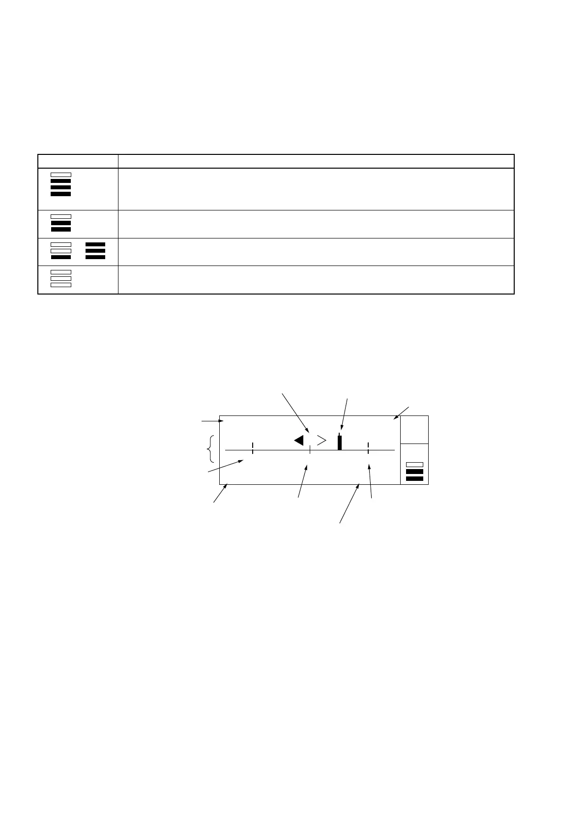
[Template Screen]
Figure 4-4 shows the template screen that visually indicates whether the frequency measurement results fail in the preset
range. This screen allows you to instantly make a decision without calculating frequency values when making adjustments.
100 000 500 Hz Go
99 999 000 Hz 100 001 000 Hz
Gate •
Auto
LOF CNF UPF
(1) Frequency display
(2) Frequency position
indicator
(3) Lower frequency
limit position
Analog display area
(4) Lower frequency
limit
(5) Upper frequency
limit position
6
U
er fre
uenc
limit
(7) Central frequency
position
(8) Result
(9) Movement direction
indicator
Fig. 4-4 Template Screen
The following describes (1) to (9) found in Fig. 4-4 above.
(1) Frequency display
Displays the results of frequency measurements.
(2) Frequency position indicator
Indicates current position of the frequency being measured within the range set in advance. This range consists of
an upper frequency limit and a lower frequency limit. If the measured frequency exceeds the LCD display range,
the frequency position indicator is held at the left or right end.
(3) Lower frequency limit position
Indicates the lower frequency limit on the LCD.
(4) Lower frequency limit
Displays the lower frequency limit value that was set.