4-31
To display the template screen, you must turn the template function On, and then set the various parameters.
Pressing the [Temp] key displays the template setup screen shown in Fig. 4-32. Pressing the [Return to Meas] key in the
displays shown below displays the measurement screen. Fig. 4-31 shows the measurement screen when the template
function is On.
20 000 000 0
00
Hz Template
Upper Limit : 20 000 000 000 Hz
Lower Limit : 19 000 000 000 Hz
Template
[On]
Upper
Limit
Lower
Limit
Indicate
[On]
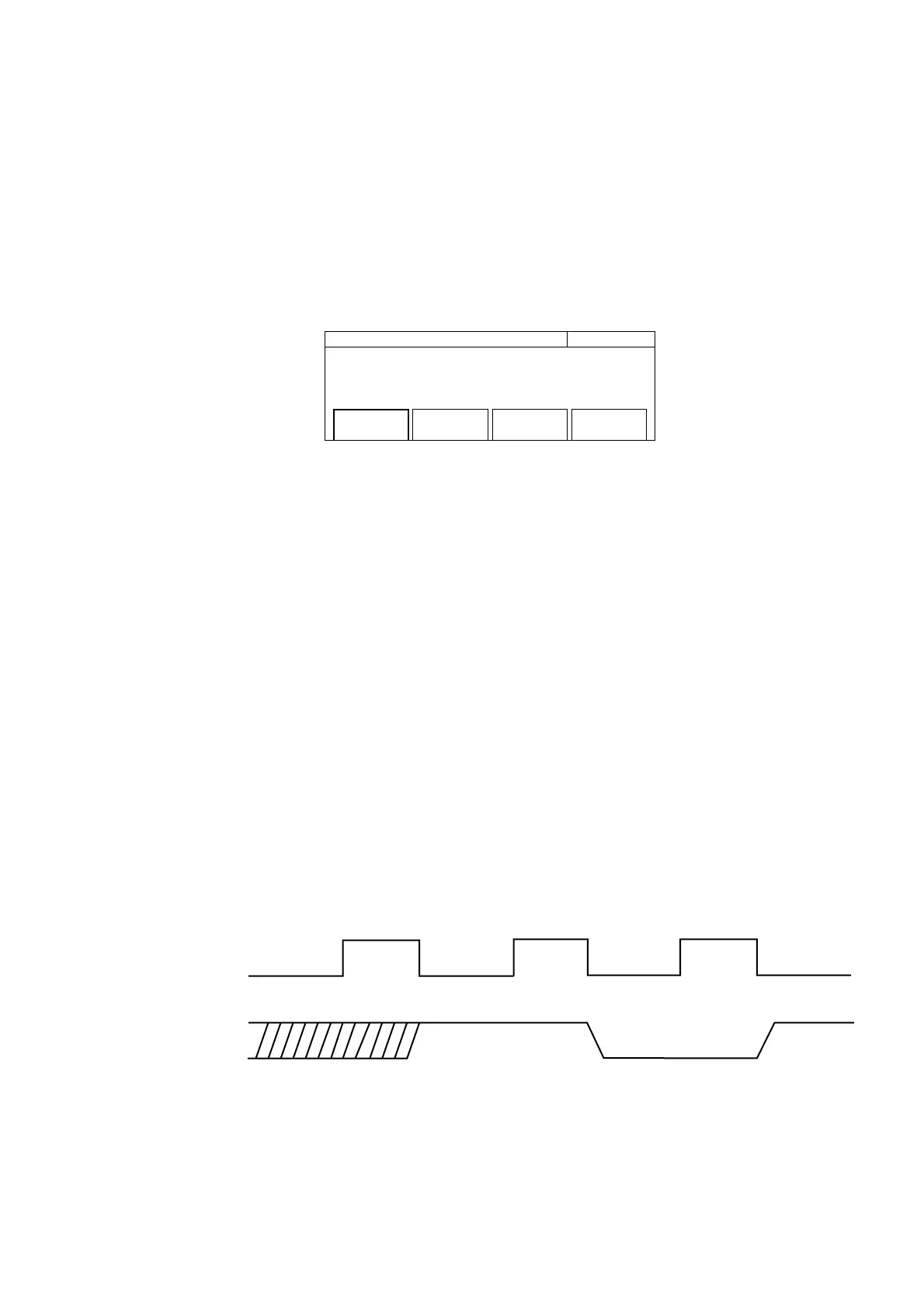
Fig. 4-32 Template Setup
(1) Menu F1 : Sets the template function to On or Off.
(2) Menu F2 : Sets the upper frequency limit using the front panel numeric keypad. Selecting Upper Limit will highlight
it so that it can be set.
(3) Menu F3 : Sets the lower frequency limit using the front panel numeric keypad. Selecting Lower Limit will highlight
it so that it can be set.
(4) Menu F4 : Turns On/Off the indicator for showing when the measurement frequency strays off of the display screen
(see Fig. 4-4). Select On to display it and Off to not display it.
The upper and lower frequency limit is between 0 Hz and Fmax set in 1 Hz units.
Note, Fmax= 20 GHz.............. MF2412B
27 GHz.............. MF2413B
40 GHz.............. MF2414B
Note :
The Go/No-Go result is stored until the following decision is made.
Measurement state
output
Measurement Measurement Measurement
Pause Pause
Go
No-Go
Go
4.3 Parameters