HARDWARE INSTALLATION
28
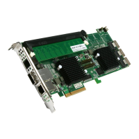
C: Global Indicator Connector
If the system will use only a single global activity/fault indicator,
attach the LED to the two pins global activity and two pins global
fault connector. The global fault pin pair connector is the overall
fault signals. The global activity pin pair connector is the overall
activity signals.
The following diagrams show the connector and pin locations.
2.6 Summary of the installation
The ow chart below describes the installation procedures for SAS
RAID controllers. These procedures includes hardware installation,
the creation and conguration of a RAID volume through the Mc-
BIOS/McRAID, OS installation and installation of SAS RAID control-
ler software.
The software components congure and monitor the SAS RAID
controllers as following table.
PIN Description PIN Description
1 Power (+5V) 2 GND
3 LCD Module Interrupt 4 Protect Key
5 LCD Module Serial Data 6 Fault/Activity Clock
7 Fault/Activity Serial Data 8 LCD Module Clock
Figure 2-9, ARC-1212/1222
Global Indicator Connector for
Computer Case.