PU-4010 1-9
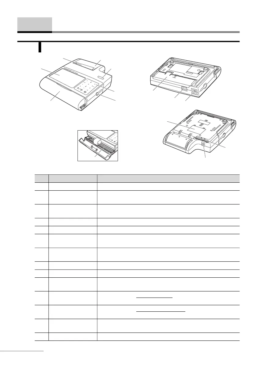
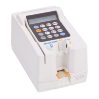
1-3-1 Instrument and Printer
Components Descriptions
1 Paper slot Printouts of results are ejected from here.
2 Display Results and error codes are viewed here. See “1-5-1. Display” on
page 1-18.
3 Reading unit cover Open this cover to perform testing. Perform test with cover closed if
an error occurs due to strong room light.
4 Printer cover Covers paper roll. Open cover to load printer paper.
5 FEED button Feeds printer paper forward.
6 Operator panel Fourteen operating buttons are provided here. See “1-5-2. Operator
Panel” on page 1-19 for a description of each button.
7 DATA output
terminal
Remove the rubber cap and attach the optional RS-232C cable
here for connection to an external device.
8 Test strip holder Holds test strip in place during testing.
9 Battery cover Open this cover to load two AA batteries.
10 Printer terminal The instrument is electrically connected to the printer via this
terminal.
11 Power input terminal
(instrument)
For AC operation without the printer, connect the plug of the AC
adapter here.
12 Power input terminal
(printer)
For AC operation with the printer attached, connect the plug of the
AC adapter here.
13 Stylus pen Use this pen to press the buttons on the operator panel if it is
difficult for you to do with your fingers.
14 Serial number Serial number of the instrument.
1-3 Components
Instrument with the printer attached
Reading unit
cover opened
13
14
Bottom of the
instrument with
the printer attached
Bottom of the
instrument
1
2
3
4
5
6
7
8
9
10
11
12