TD 92483GB
2008-06-05/ Ver. B
Installation and Operation Manual
UPAC- Unite Packet for Messaging and Alarm
8
2.7 Accessing the UPAC
2.7.1 Getting Started
When accessing UPAC the first time, follow the instructions in the Assembly Card, Getting
Started M0276300 (enclosed in delivery), or see Appendix E on page 95 which holds a
copy of the printed leaflet.
Note: The IP address must not change during operation because renew of IP address via
DHCP is not handled. Other equipment connected to this product also expects a fixed IP
address in some cases. If the IP plan is changed, this product must be restarted to update
the IP address. Otherwise there is a risk for IP address collision.
Note: Attach the ferrite bead on the power supply cable. Follow the enclosed assembly
card for EMC protection, M0271500.
2.7.2 Connect Cables
A cable to the DECT Exchange can be ordered separately, refer to the Data Sheet UPAC –
Unite Packet for Messaging and Alarm TD 92482GB. If you want to make your own cable,
refer to the descriptions in Appendix B: RJ45 Connections on page 84.
For connections to digital inputs/outputs and the error relay, refer to 2.3 Connection of
AUX Inputs and AUX Outputs and 2.4 Error Relay Output on page 6.
1 Break off suitable sections before inserting cables, refer to 2.2 Mounting on page 4.
2 Connect the DECT Exchange or GSM modem to connector J11 (RS232:1).
3 Connect external equipment to connector J7 (RS232:3).
4 For remote management use connector J8 (RS232:2).
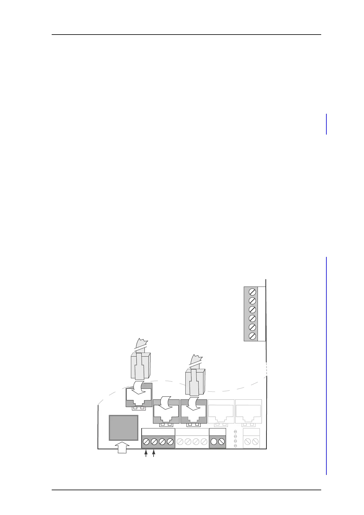
Figure 5. Cable connections
Figure 9.
J13
J12
J11
J8
J7
J24
J14J6J5
J20
RS232:3
ETH
900 900RS232:2
S4
S5
S1
S2
2
21
1414 1
DECT Exchange or GSM modem
LAN or PC
+12V GND
Error relay
output
008
1 External +12 V
2 IN1
3 IN2
4 OUT1
5 OUT2
6 External GND
J16
AUX Inputs/ Outputs
External equipment
(ESPA 4.4.4 / Line protocol)
RS232:1
Remote
management