TD 92483GB
2008-06-05/ Ver. B
Installation and Operation Manual
UPAC- Unite Packet for Messaging and Alarm
6
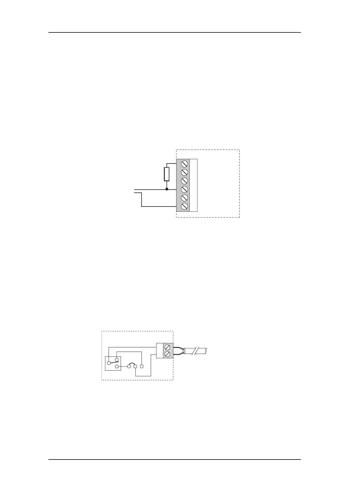
2.3 Connection of AUX Inputs and AUX Outputs
Two digital inputs and two digital outputs can be connected via connector J16. The inputs
can be used as trigger conditions, by for example connecting a switch or a button which in
turn can use the outputs for actions, for example to turn on a siren or to close a door.
The outputs are of open-collector type and the output signals are dimensioned for
100 mA at max. 12 V. A pull-up resistor should be connected to the output as shown in
figure 3.
Galvanic isolation of the inputs and outputs is provided by using a separate power supply.
When galvanic isolation is not needed, supply voltage can be taken from the UPAC circuit
board by connecting J16-1 to J5-3 and J16-6 to J5-4.
Figure 3. Connection of inputs and outputs.
The inputs IN1 and IN2 are active when they are connected to 12 V. When the output
OUT1 is active, the potential in point A in figure 3 will be close to 0 V. The same applies for
a similar connection for OUT2.
The internal inputs and outputs are predefined in UPAC. Refer to 4.5 Input/Output Setup
on page 18.
2.4 Error Relay Output
The relay output on connector J14 is used to indicate UPAC malfunction and can also be
used to indicate other errors. Refer to 10.2 Fault Handling on page 48. See also Appendix
C: Fault Handling Configuration Example on page 86.
Figure 4. Jumpering decides when the error relay output is active.
The jumpering J15 decides if the output shall be active when the relay is operating or
released. 1-2 selects operating and 2-3 selects released. In figure 4 the relay is released
and, as the jumpering is set to 1-2, the circuit is open and the error relay output is inactive.
At power-up or restart of the UPAC, the relay is released until the applications are working
properly. If the relay is released longer, UPAC is malfunctioning.
Figure 6.
Figure 7.
1 External +12 V
2 IN1
3 IN2
4 OUT1
5 OUT2
6 External GND
J16
005
Pull-up
resistor
External
equipment
A
2
1
J14
RE1
321
J15
Error relay output
006