TD 92483GB
2008-06-05/ Ver. B
Installation and Operation Manual
UPAC- Unite Packet for Messaging and Alarm
79
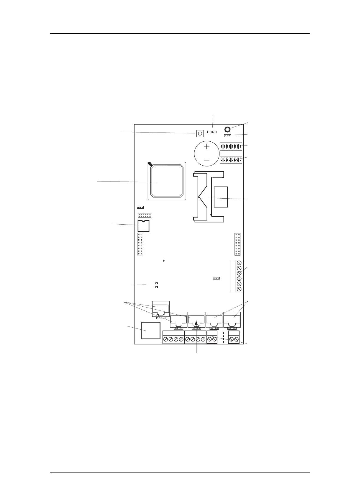
14 Troubleshooting
14.1 Built-in tools in UPAC
The UPAC hardware has different LEDs to indicate the status and besides that the
possibility to show active faults and logging the faults.
Figure 42. UPAC Circuit board
Figure 105.
Tools Description
Function Indicator Refer to the table 2.5 Function LED Indications on page 7
LED6 ON: Communication on Ethernet
LED7 ON: 100MBit/s
OFF: 10MBit/s
J2
IC2
J10
J16
J15
J4
J13J12J11J8
J7
J24
J14J6J5
J20
S3
LED6
RS232:3
ETH
900 900RS232:2 RS232:1
LED7
S4
S5
S1
S2
IC24
J22
J9
IC1
CPU
BAT1
SW4
LED
LED1
J1
SW2
SW3
1
1
8
1
8
1
6
2
21
1414 1
2 3 4 5
Status LEDs
Function indicator
Battery activation
900 address
Configuration
Compact Flash
I/O connectors
900 Bus
Error Relay connector
Shut down CPU
CPU
Module Key
Ethernet Status LEDs
RS232 connectors
Ethernet connector
DECT or GSM
093