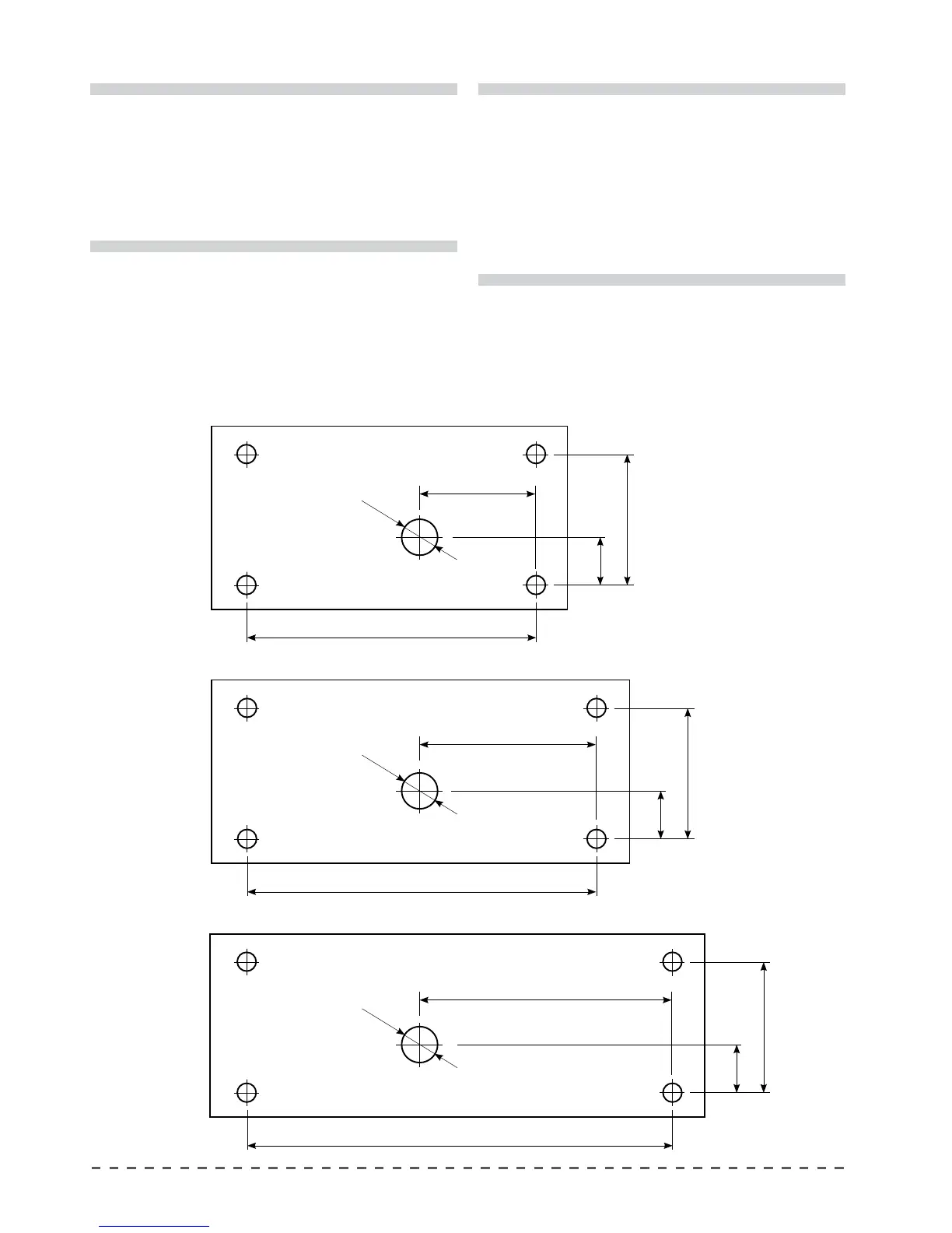
3.3 Drilling holes on the support bench
In the case where it is necessary to drill holes on the support bench for passing the water inlet and outlet hoses,
as well as the electrical and gas supply cables, follow the directions in the drawings below.
4 GROUPS
400 mm
1016 mm
Front of the machine
382 mm
200 mm
80 mm
3 GROUPS
300 mm
776 mm
Front of the machine
382 mm
200 mm
80 mm
2 GROUPS
200 mm
536 mm
Front of the machine
382 mm
200 mm
80 mm
!
During the installation of the appliance, only
the components and materials supplied with the
appliance are to be used. Should the use of other
components be necessary, the installer must
verify their suitability to be used in contact with
water used for human consumption. The installer
must carry out the hydraulic connections in
accordance with the hygiene norms and the
hydraulic safety norms for environmental
protection in force in the place of installation.
!
FOR THE U.S.A.
The water connections and discharges must be
made in accordance with the 2003 International
Plumbing Code of the International Code Council
(ICC), or with the 2003 Uniformed Hydraulic Code
of the IAPMO. The machine must be installed
together with an adequate non-return valve, as
required by national regulations.