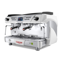
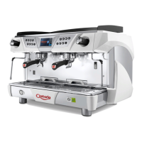
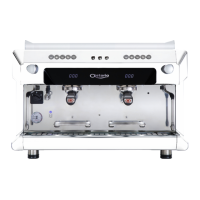
4.8 Pumping system
This is a component that feeds the machine, raising
the water pressure to 8-9
bar for coee delivery and
automatic filling of the
boiler.
4.9 Valve group
The valves are devices whose purpose is to ensure the
safety and proper operation of the machine.
4.9.1 Pressure limitation safety valve
The pressure relief valve guarantees that
the pressure in the boiler does not go above
2 bar. If there is a malfunction, the valve can
eliminate all the excess pressure from the
boiler.
4.9.2
Expansion - non-return valve
This is a valve consisting of an expansion valve and
a non-return valve.
• Expansion valve (1): the cold water sent from the
pump to the heat exchangers is heated. This heat-
ing causes an increase in the volume of water. To
limit pressure increases in the hy-
draulic circuit, the valve limits the
maximum internal pressure of the
circuit to 12 bar.
• non-return valve (2): Its function
is that of preventing the back ow
of water from the exchangers in
the hydraulic circuit.
4.10 Electric control unit
The electronic control unit is the nerve center of the
machine. It monitors and controls all operation of the
unit.
The information related to the installed
software (date and version) can be seen on
the display when the machine is turned
on. the monitoring and control of the
entire functioning of the machine.
The information concerning the
installed software (date and version) can
be seen on the display when the machine
is turned on.
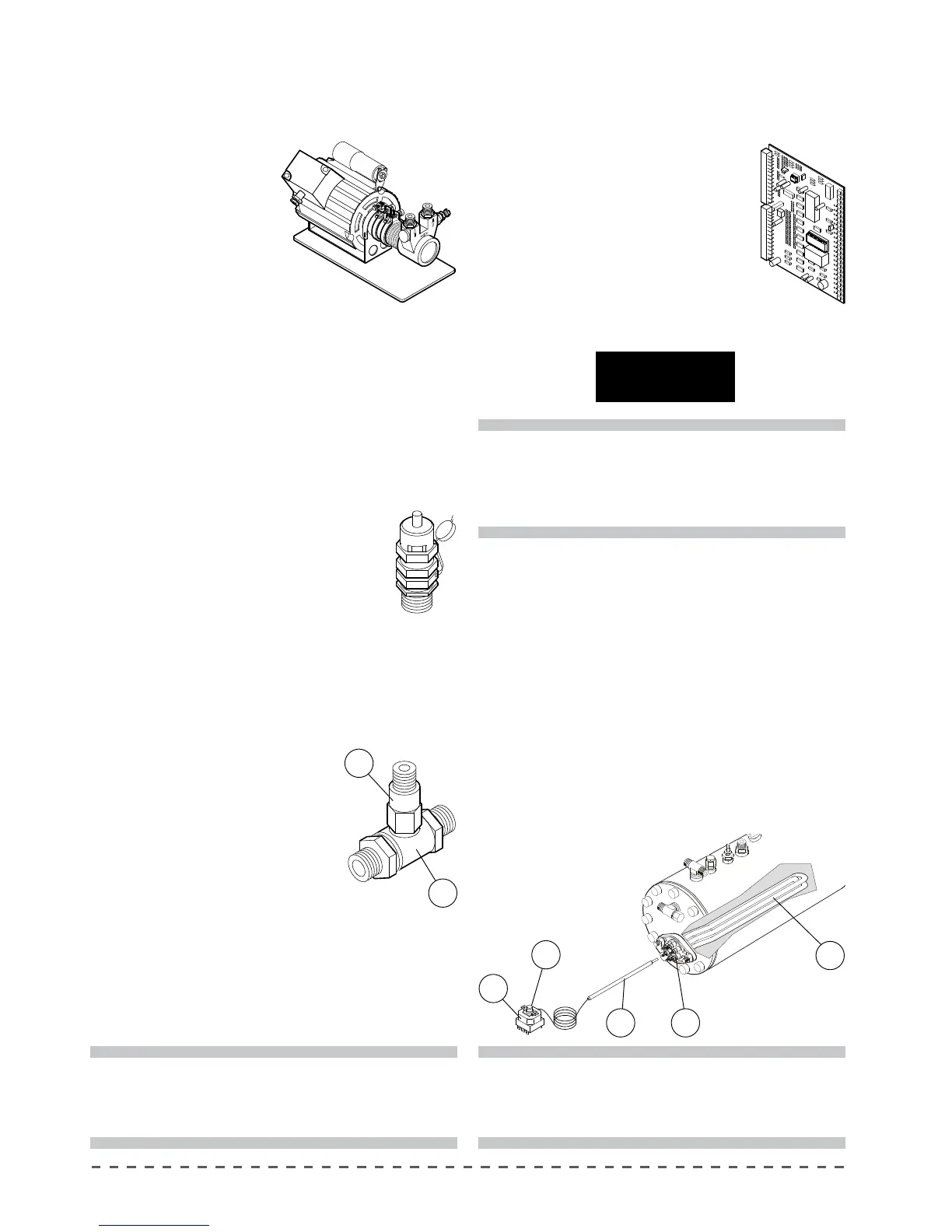
4.11 Thermostat
The thermostat allows you to avoid damage to the
electrical resistance in case of lack of water in the boiler.
The thermostat bulb (7) is located inside a sheath (8)
placed at the center of resistance. The contacts of the
thermostat (9) are connected to the electrical resistance
(10). If the electrical resistance is exposed due to
failure to load water to the boiler, the temperature of
the resistance increases dramatically. At this point, the
thermostat interrupts the power supply to the resistance
thus preventing damage.
1
2
DATA
REGISTER RESET
11
9
7 10
8
!
When the software is updated, as soon as the
machine is started the system loads the default
data. In this case you will need to set the machine
parameters again.
!
To reset the thermostat, press the center button
(11). However, before trying to operate the
machine, verify the causes of the blockade of the
water feeding the boiler.
!
The valves must be checked on a regular basis as
described in the chapter "Controls and maintenance".