EasyManuals Logo

ASUSTeK COMPUTER GigaX3112 Series User Manual

Default Icon
118 pages
To Next Page IconTo Next Page
To Previous Page IconTo Previous Page
Page #19 background imageLoading...
Page #19 background image
6
GigaX3112 Series Layer 3 Managed Switch
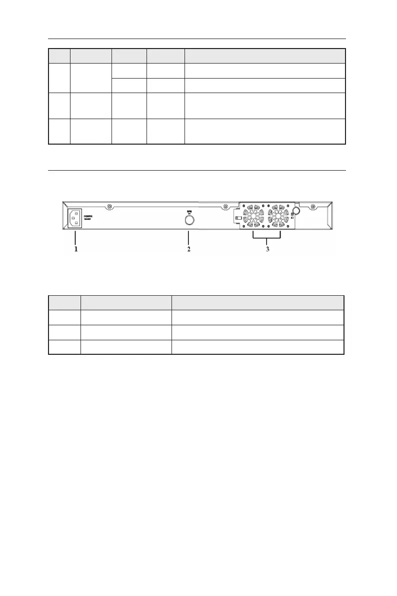
Figure 3. Rear panel
Table 2. Rear panel labels
No. Label Description
1 Power Connects to the supplied power cord
2 RPS Redundant Power Supply connector
3 FAN1 – FAN2 Replaceable system fans
No. Label Color Status Description
6 Duplex
status
Green ON
Full duplex
Amber ON
Simplex
7 Console
USB
USB port for console
8 Console
RS232
RS-232 serial port for console
2.3 Rear panel
The switch rear panel contains the swappable fans and power connections.

Table of Contents

Questions and Answers:

Question and Answer IconNeed help?

Do you have a question about the ASUSTeK COMPUTER GigaX3112 Series and is the answer not in the manual?

ASUSTeK COMPUTER GigaX3112 Series Specifications

General IconGeneral
BrandASUSTeK COMPUTER
ModelGigaX3112 Series
CategorySwitch
LanguageEnglish