10
GigaX3112 Series Layer 3 Managed Switch
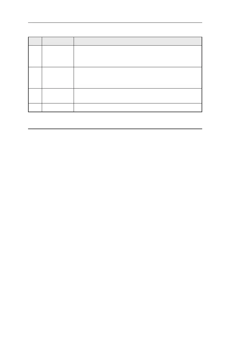
Table 4. LED Indicators
No. LED Description
1 System Solid green indicates that the device is turned on. If this
light is off, check if the power adapter is attached to the
switch and plugged into a power source.
2 Switch ports
[1] to [12]
Solid green indicates that the device can communicate
with the LAN, or flashing when the device is sending or
receiving data from your LAN computer.
3 RPS Solid green indicates that the device has successfully
installed an RPS module.
4 Fan Solid green indicates that all fans work properly
3.3 Part 3 — Basic switch setting for management
After completing the hardware connections, configure the basic settings for your
switch. You can manage the switch using the following methods:
• Web interface: the switch has a set of pages to allow to you manage it using
Java®-enabled IE6.0 or higher version.
• Command Line Interface: use console port to manage the switch.
3.3.1 Setting up through the console port
Use the supplied crossover RS-232 cable to connect to the console port on the
front right corner of the switch. This port is a male DB-9 connector, implemented
as a data terminal equipment (DTE) connection. Tighten the retaining screws on
the cable to secure it on the connector. Connect the other end of the cable to a
PC running terminal emulation software. e.g Hyper Terminal.
Use the supplied USB cable to connect to a PC. You have to install the USB
driver from the switch CD-ROM before the USB can work properly. The USB
drivers will simulate an additional COM port under Windows Me/2K/XP OS.
Make sure the settings of your terminal emulation software as follows:
Choose the appropriate serial port number
Set the data baud rate to 9600
Set the data format to no parity, 8 data bits and 1 stop bit
No flow control
Set VT100 for emulation mode
After setting up the terminal, you can see the prompt “ASUS login:” on the terminal.
 Loading...