21
GigaX3112 Series Layer 3 Managed Switch
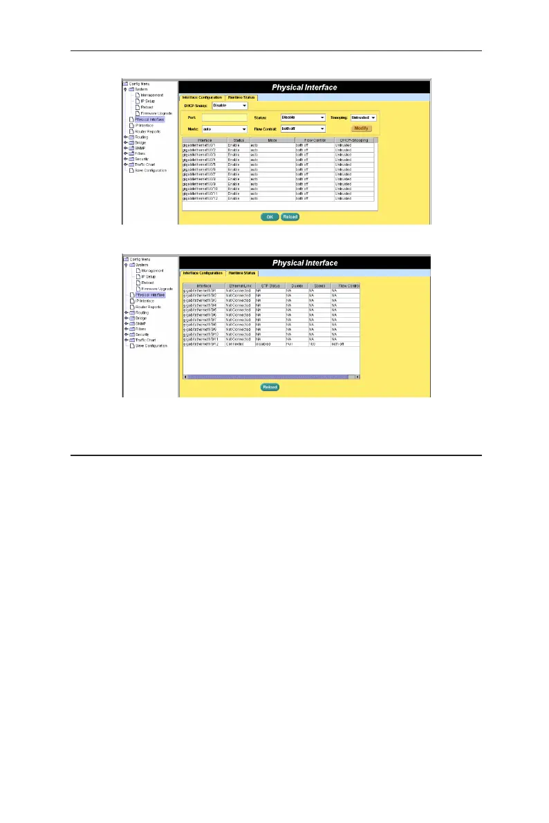
Figure 18. Physical interface 1
Figure 18. Physical interface 2
4.5 Bridge
The Bridge page group contains most layer 2 configurations, like link
aggregation, STP, etc.
4.5.1 Spanning tree
The page configures three types of Spanning Tree Protocol.
4.5.1.1 STP Status
The first page “STP Status” can disable or enable STP. There are three modes
STP, RSTP and MSTP can be enabled. If MSTP is enabled, the following four
attributes are enabled at the same time:
Region Name:
An alphanumeric configuration name
Revision:
A configuration revision number
Instance ID:
A STP instance, you can configure MSTP on your switch to
map multiple VLANs into a single STP instance.
VLAN Group:
A group associates each of the potential 4094 VLANs to the
given instance
 Loading...