16
GigaX3112 Series Layer 3 Managed Switch
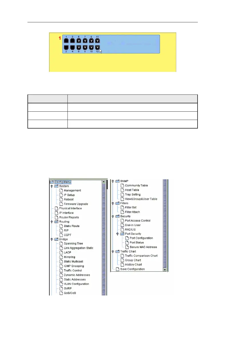
Figure 13. Selection Panel (GigaX 3112)
Table 5. Port color description
Port Color Description
Green port Ethernet link is established
Black No Ethernet link
Amber port Link is present but port is disabled manually or by spanning tree
Clicking on the port icon of the switch displays the port configuration in the lower
right frame.
The left frame, a menu frame as shown in Figure 14, contains all the features
available for switch configuration. These features are grouped into categories,
e.g. System, Bridge, etc. You can click on any of these to display a specific
configuration page.
Figure 14. Expanded menu list
 Loading...