Ch. 8. Conductive AFM (ORCA) Sec. 8.5. Testing the ORCA Amplifier
1.
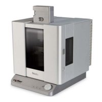
Install the test resistor under the clip on the
ORCA holder
• Hold the ORCA holder upside down in
you hand and use a fingernail to press
on the button on the top side of the
holder to open the cantilever clip.
• Slide the resistor lead under the clip.
• Release the button to clamp onto the
resistor lead.
Note Using the changing stand also works
but you may find that getting the resistor
installed and removing the holder from the
stand is a bit tricky. Using your fingers as
described works well.
Note The cantilever holder body is
conductive. Position the lead under the clip so
that is does not touch the holder body.
Basically, take care not to insert the resistor
lead too far under the clip or have it off center.
Note It is not harmful if the resistor shorts to
ground. The current from the sample bias
through the resistor will not be measured by
the holder.
2.
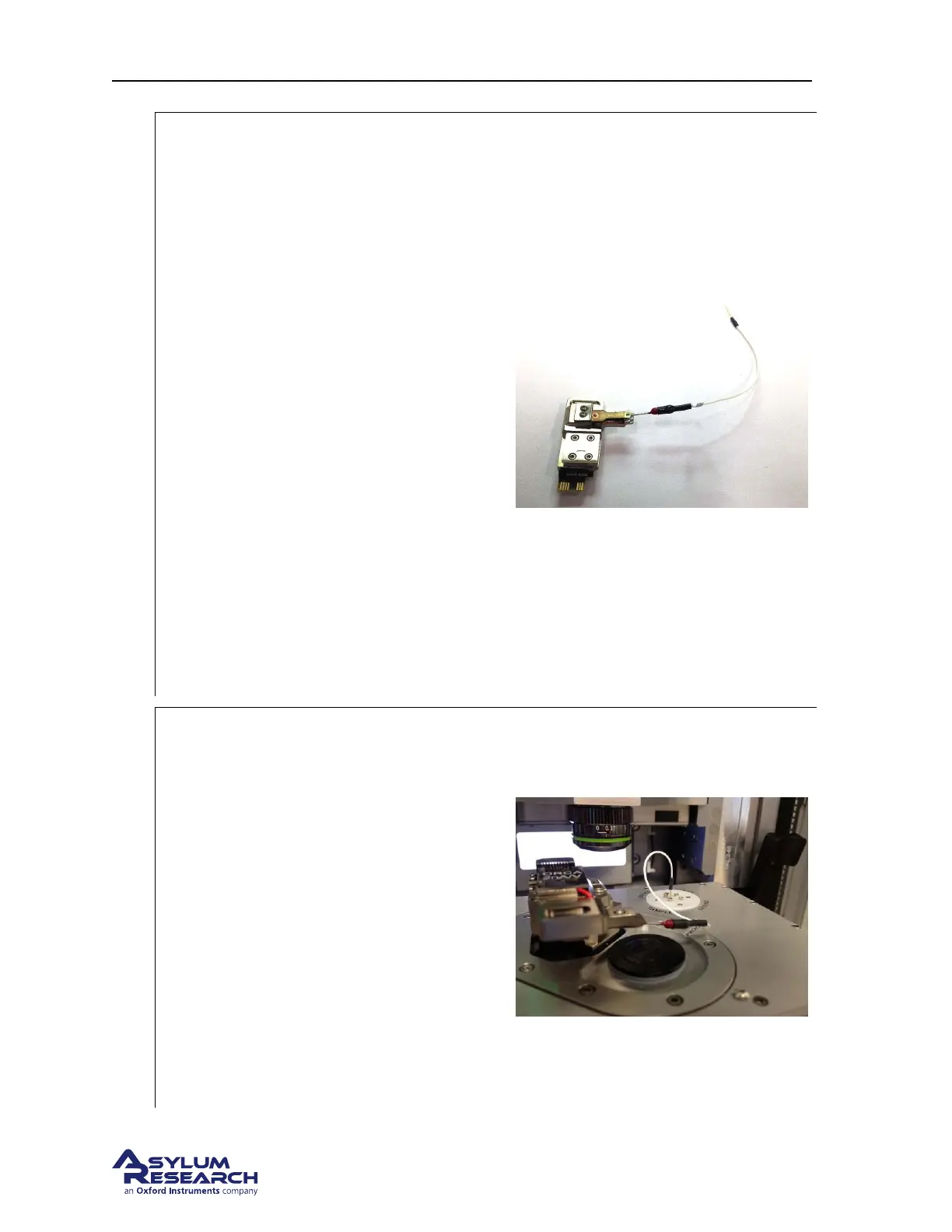
Install the cantilever holder and connect the
test resistor to sample bias
• Insert the ORCA holder into the
scanner’s engage pillar.
• Plug the lead from the test resistor into
the sample bias socket on the scanner’s
terminal block.
• Slide the scanner into the chassis and
close the enclosure door.
Note You may wish to double check the lead
under the cantilever clip to ensure it is not
shorted to the holder body.
Note The enclosure acts like a Faraday shield
which will help reduce outside electrical
noise.
DRAFT
Page 100