Ch. 8. Conductive AFM (ORCA) Sec. 8.2. The ORCA Amplifier
Itm Part # Item Description Qty Picture
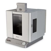
7 448.082
Cypher ORCA 500M Resistor
Assembly. A 500M Ohm Test
Resistor. See Section 8.5 on
page 99.
1
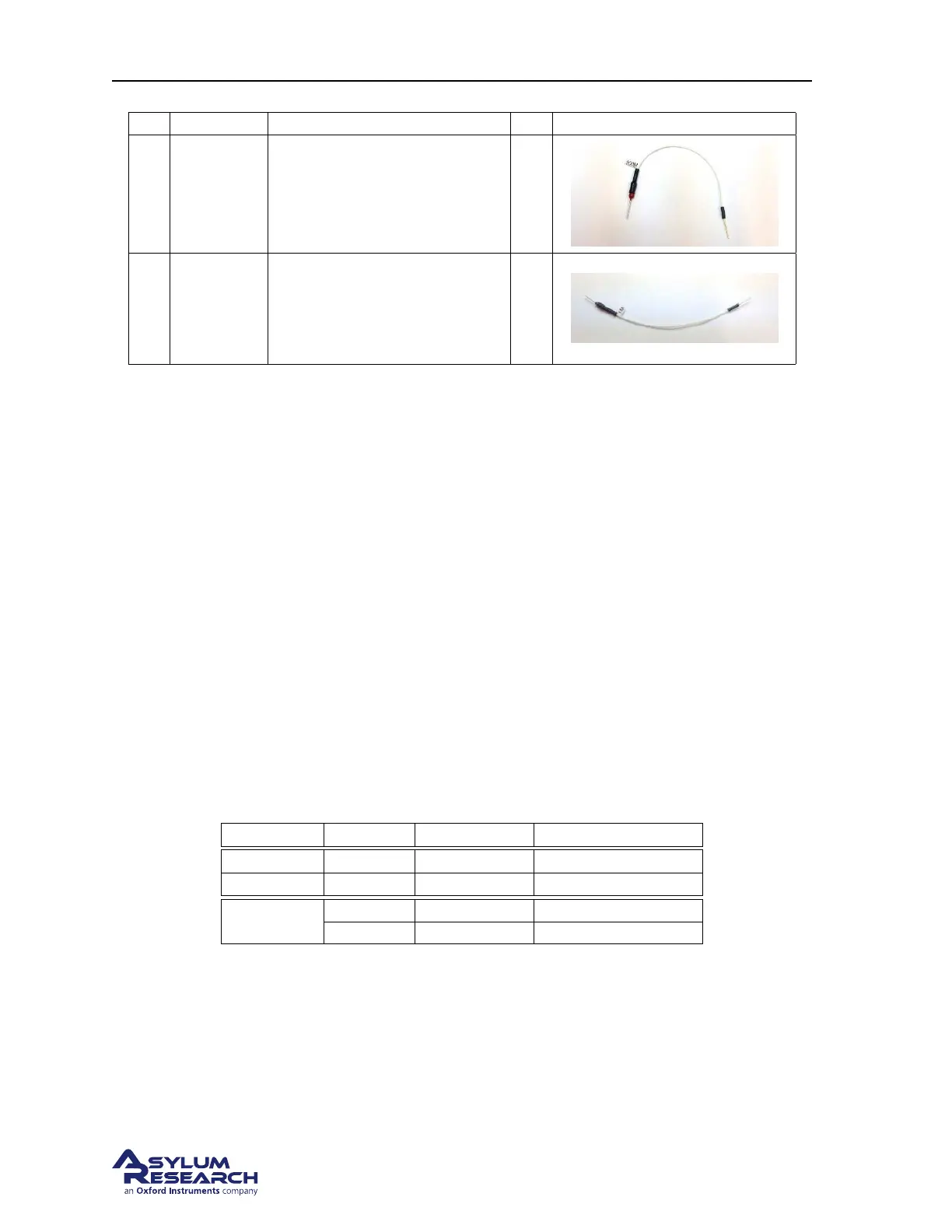
8 448.081
Cypher ORCA 1M Resistor
Assembly. A 1M Ohm Test
Resistor (Dual Gain ORCA
Only). See
Section 8.5 on
page 99.
1
8.2. The ORCA Amplifier
There are a variety of ORCA cantilever holders each based on either a single or dual amplification
design. The design type and amplification gain are labeled on the top of the holder. Like all the Cypher
cantilever holders, a built-in circuit in the holder allows the software to automatically sense the type of
holder and configure the system accordingly.
The amplification range of the ORCA amplifier is expressed by it’s sensitivity. Basically the ability to
produce a voltage output from a certain current flow into the tip. In terms of the full range of the ORCA
amplifier, the output is +/-10v so multiplying the sensitivity by +/-10 will tell you the full range.
The ORCA amplifier incorporates the use of a trans-impedance amplifier which converts the input cur-
rent from the tip to an output voltage. The input potential of the amp is referenced to ground so the tip
is essentially held at 0v potential. During the measurement, the sample can be biased between +/-10v
using a voltage source provided by the Cypher electronics.
Each ORCA cantilever holder has a fixed gain(s) to provide the highest current measurement range while
considering the lowest noise. The following ORCA holders are currently available. Custom holders can
be configured on request.
Part number Sensitivity Current Range Typical noise 1-1KHz
901.730 2nA/V +/-20nA 1.5pA
901.737 0.2nA/V +/-2nA 750fA
901.708
1nA/V +/-10nA 3pA
1uA/V +/-10uA 75pA
8.2.1. Single Gain
Here is a conceptual block diagram of the single gain ORCA amplifier. The sample is biased from a
voltage source within the Cypher electronics. The feedback resistor R1 sets the amplifier’s sensitiv-
ity. The output signal representing tip/sample current flow can be monitored by enabling the ’Current’
channel in the master channel control panel. See
Figure 8.1 on page 95.
DRAFT
Page 94