Ch. 8. Conductive AFM (ORCA) Sec. 8.2. The ORCA Amplifier
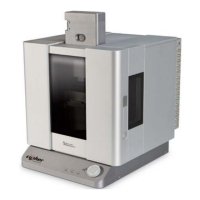
Sample Bias
Feedback
Resistor
Sample
I to V
Current
Figure 8.1.: Single Gain ORCA
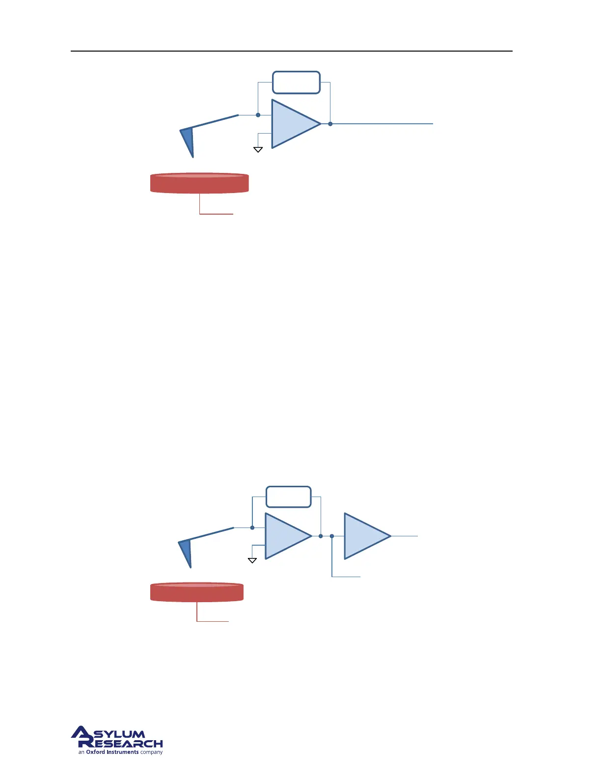
8.2.2. Dual Gain
A conceptual diagram of the dual gain ORCA amplifier shows the initial current to voltage converter
stage feeding the input of a second gain stage to create an additional output signal. In the case of this
design the more sensitive signal comes from the second stage and is monitored as ’Current’ from the
master channel panel like the single gain ORCA holder.
The output of the current to voltage amplifier’s first stage has a lower gain (more total current range)
signal is monitored as ’Current 2’ from the master channel panel.
Having a dual gain design is useful in that it expands the dynamic range of your measurement capability
but at a sacrifice of some increased noise at small current levels. In many cases the sample you may
wish to measure may have widely different regions of conductivity where the current may be too large
for the range of the more sensitive stage but suitable for the lower gain stage where more current can
me measured. In this case it is common to see the ’Current’ signal (high gain stage) saturate while the
’Current 2’ signal show a measurable current flow. See
Figure 8.2 on page 95.
Sample Bias
Feedback
Resistor
Sample
I to V
Current
Current2
G=1000
Feedback
Resistor
Figure 8.2.: Dual Gain ORCA
DRAFT
Page 95