Ch. 8. Conductive AFM (ORCA) Sec. 8.4. Imaging with the ORCA
2.
Adding resistance in the bias voltage path
• In cases where your sample is highly
conductive, you may want to add a
known resistance to keep the OR CA
amplifier from saturating. An example
of this is the HOPG sample provided in
the kit.
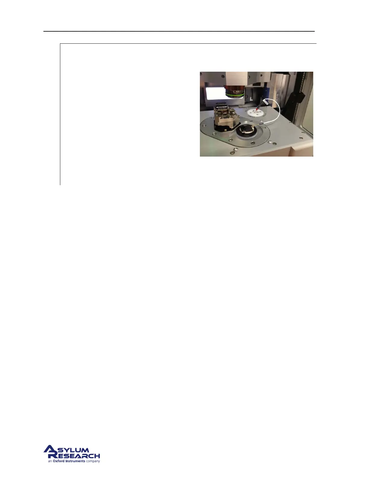
• Substitute the Bias lead with a bias lead
including a resistor.
Note The ORCA holder kit includes a
500Meg. Ohm test resistor. If you are
planning on scanning the HOPG sample to
practice using the ORCA holder, use the test
resistor instead of the bias lead.
8.3.3. Mounting the Cantilever
Mounting a cantilever is the same procedure as is used in all other AFM applications with the exception
of lever type. Conducting AFM (ORCA) requires a conductive path between the tip and the cantilever
spring clip. The ORCA kit includes a sample pack of 10 Electrilevers. Additional levers can be pur-
chased from Asylum Research.
If you are not familiar with basic AFM operating practices, please review The basic operating tutorials
section at the beginning of this guide.
8.4. Imaging with the ORCA
Please refer to Applications Guide, Chapter: Conductive AFM.
8.5. Testing the ORCA Amplifier
The ORCA cantilever holder kit includes an appropriately sized resistor to test the measurement range of
the ORCA amplifier. Testing the ORCA is fairly straight forward. Basically the test resistor in installed
between the sample bias and the cantilever clip. An I/V ramp is plotted and the correct current flow
through the resistor should be observed.
DRAFT
Page 99