Ch. 8. Conductive AFM (ORCA) Sec. 8.3. Preparing for Imaging
8.3.2. Preparing the Sample
Sample preparation varies but basically the goal is to provide an electrical path between the sample bias
and the surface of your sample. In addition to the electrical connection, care should be taken to mount
the sample mechanically to a sample puck as you would with any sample.
The ORCA kit comes with a practice sample of graphite (HOPG) mounted to a steel puck. A small
magnet is attached to the sample puck to provide an easy way for the bias lead to attach.
The magnetic connection method is convenient but is not necessary. A bias lead of your own design
can be mounted directly to the sample puck and used as long as the end of the lead is able to fit into
the sample voltage socket on the scanner’s terminal block. Also, be certain to use wire that is flexible
enough to not impede normal scanning.
The following steps describe how this sample was prepared.
1. Use a small amount of 5 minute epoxy to attach the HOPG to the sample puck.
2. Place a magnet onto the puck.
3. Cover the sides of the sample and the entire magnet with silver paint.
Attention
The silver paint is not an adhesive. It will not provide good attachment of the
sample to the sample puck. Use the paint only to make an electrical connection
from the sample to the bias voltage lead.
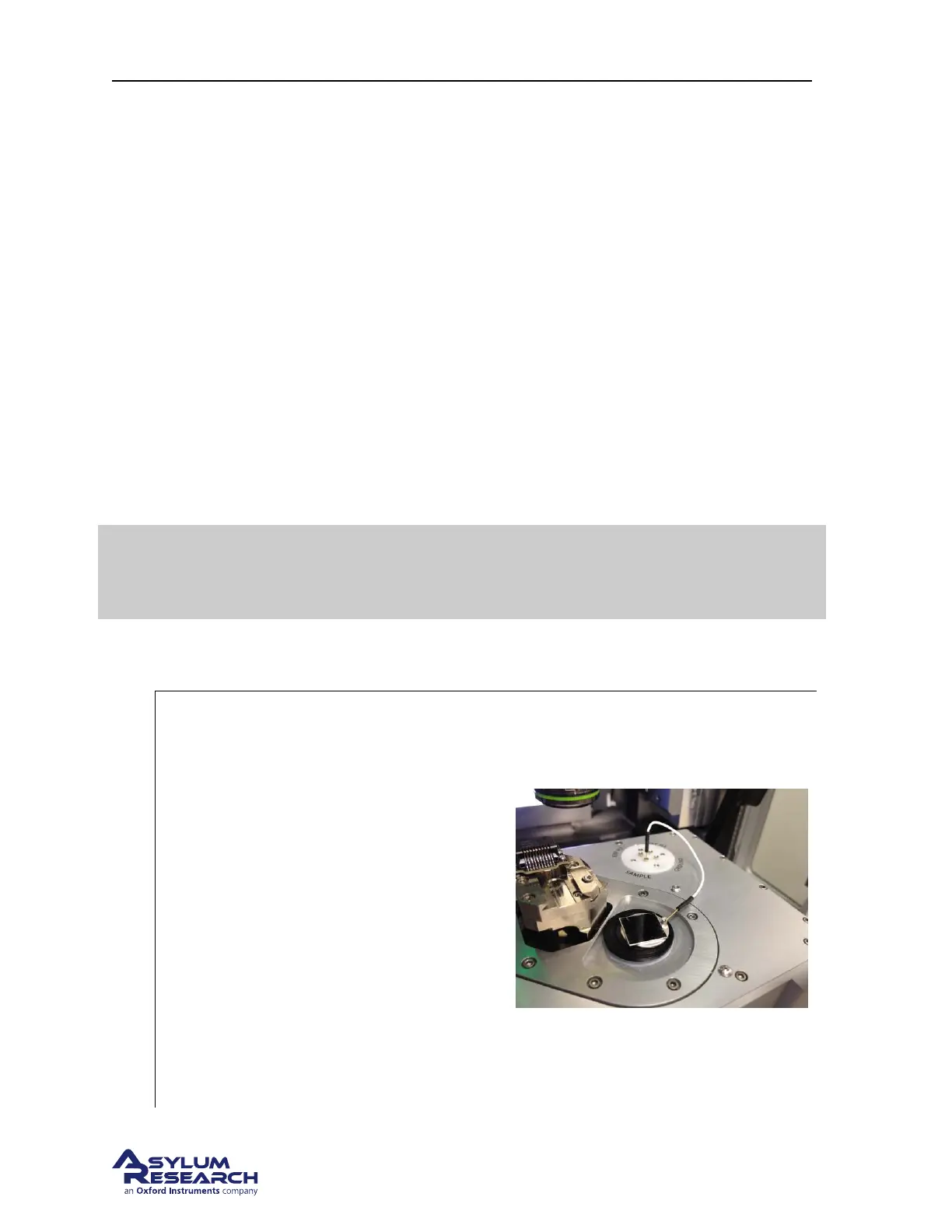
8.3.2.1. Install the sample on the scanner and connect the bias lead
1.
Place the sample on the scanner stage and
connect the bias lead
• Position the sample so that the magnet
is on the right hand side of the scanner
to prevent interference with the
cantilever holder.
• Plug on end of a bias voltage lead into
the sample socket on the terminal block.
• Place the other end of the lead on the
magnet. The lead is magnetic and will
stick to the magnet when it’s close
enough.
Note The scanner cap is hard anodized and
will insulate the the sample puck so bias
voltages up to +/-10v can be directly
connected without additional insulation.
DRAFT
Page 98