DescriptionSignal
FQM has reached end position CLOSED at the output drive side.
FQM end pos. CL
The result of the diagnostics via winding switch is available as fault.
FQM FS diag. result
Winding was not completed within the permissible initialisation time of 2.5 minutes.
FQM timeout winding
The end position switch was not active within the permissible waiting time of 10 seconds.
FQM timeout limit
The permissible tolerance range for the internal temperature or the voltage range of the respective FQM
unit was fallen short of or exceeded or the permissible tolerance range for 24 V DC at ESD input was
fallen short of or exceeded for a duration of minimum 1 second.
FQM fault temp.-volt.
The signal is generated if one of the following conditions applies:
●
FQM FS-ESD request not active AND FQM timeout winding or FQM timeout limit or FQM timeout
motor active
●
FQM FS-ESD request not active AND FQM FS ready active AND FQM FS-PosOk not active
●
FQM FS-ESD request not active AND FQM FS ready not active AND FQM FS-PosOk active
●
FQM FS-ESD request not active AND FQM fail safe ini. executed AND (FQM FS-PosOk not active
OR FQM FS ready not active)
●
FQM FS-ESD request active AND FQM FS ready active
FQM fail safe flt
The electric motor does not rotate during an initialisation operation.
FQM timeout motor
This signal will be activated if at least on the lifetime accounts (in %) has passed the activation threshold
configured for this signal.
This signal can be configured (parameter Maintenance required M0871) and comprises a combination
of the following signals:
●
Mainten. mechanics
●
LPV SA-CLOSE
●
Mainten. lubricant
●
Mainten. contactors
●
Mainten. interval
Maintenance reminder
MPV (Multiport Valve)/LPV (Lift Plug Valve) position reached.
MPV/LPV pos. reached
The operation via the push buttons on the local controls is disabled.
Disabled
The actuators runs while the indication light for the respective direction of operation (OPEN/CLOSE) is
blinking simultaneously at local controls.
Runs_OP/CL+blinker
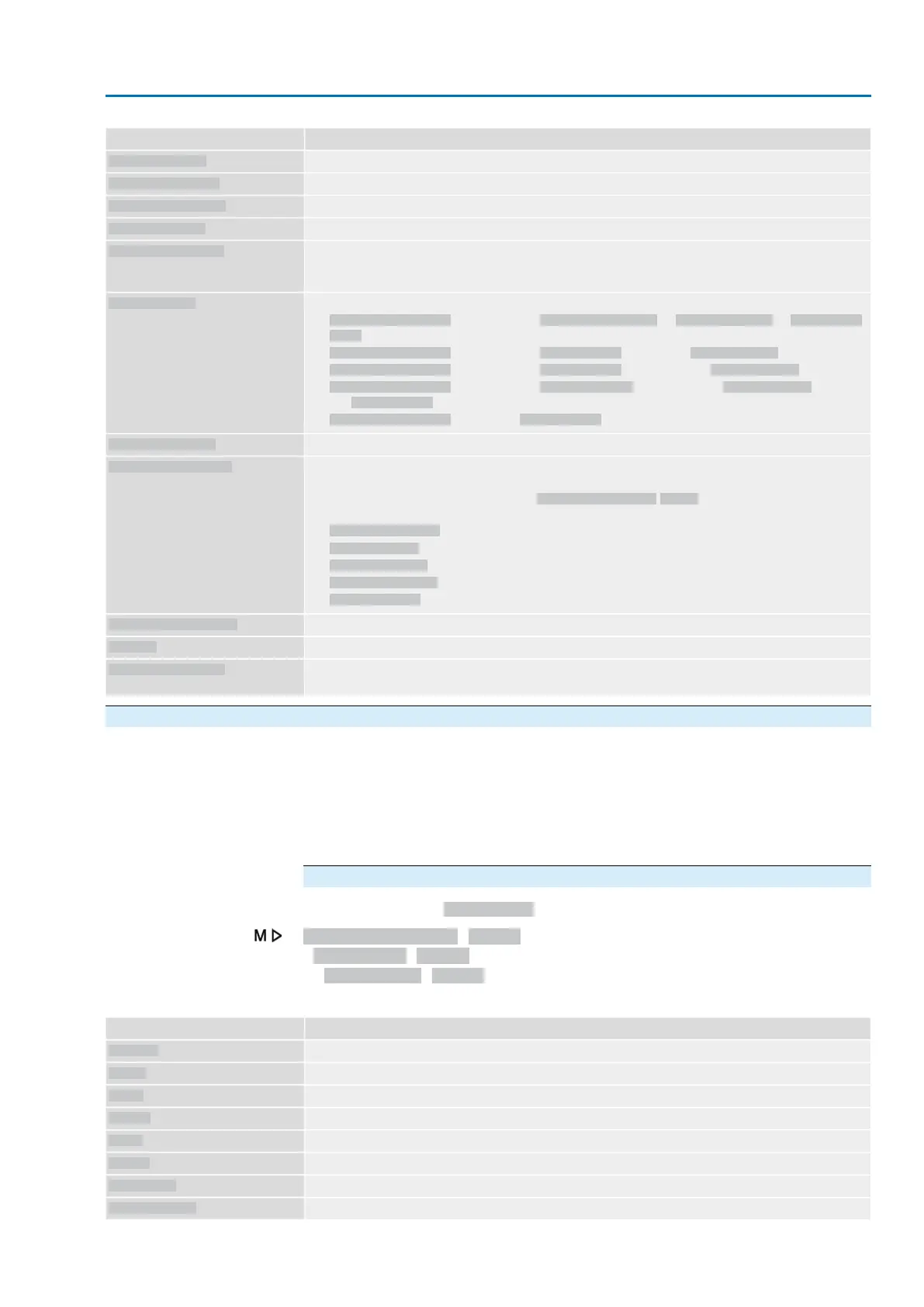
17.2. Selection list of binary signals for digital inputs (DIN)
Conditions:
<Additional inputs> or additional <Parallel interface>
Depending on the version, the actuator controls are equipped with up to 10 digital
inputs.
The inputs are designed for binary signals (standard input level: +24 V DC) and can
be used, for example, to receive operation commands OPEN, STOP, CLOSE, to
control intermediate positions or for the EMERGENCY signal.
Configuration of digital inputs
Required user level: Specialist (4).
Device configuration M0053
I/O interface M0139
Digital inputs M0116
Table 29:
DescriptionSignal
Input not assigned
Not used
Change-over between OPEN - CLOSE control and setpoint control
MODE
Operation command OPEN
OPEN
Operation command CLOSE
CLOSE
Operation command STOP
STOP
Reset fault signal
RESET
Change-over between fieldbus interface and parallel interface
I/O interface
Operation command OPEN/CLOSE for two-wire control
OPEN / CLOSE
147
Actuator controls
AC 01.2/ACExC 01.2 Profinet Appendix