Cable Connections
Installation Handbook, Autroprime Interactive Fire Detection System, 116-P-APRIME2-INSTAL/DGB, Rev. C, 2016-29-02,
Autronica Fire and Security AS
Page 25
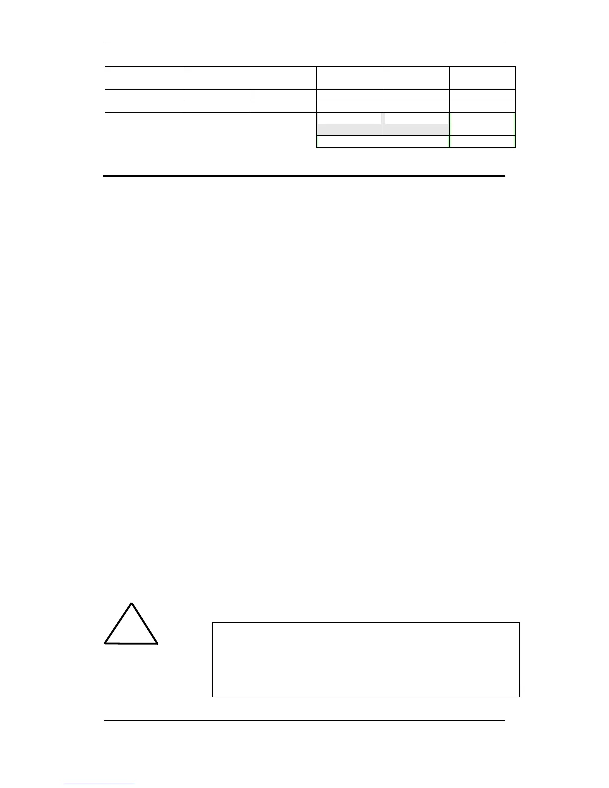
Output 2, 10
pcs
0 200 0 0,10 0,10
External load 100 200 2,40 0,10 2,50
9,82 0,66 Total:
10,48Ah
15% margin ~12Ah
9. Cable Connections
9.1 Cabling - Overview
Consult the drawings on the next pages and follow the procedure
below.
NOTE: For specific information on the installation and cable
connections for maritime installations, refer to chapter 10.
Fire Alarm Control Panel (BS-200, BS-200L, BS-200M)
Insert the rubber glands (delivered with the panel) into the suitable
cable inlets at the top. This should be done regardless of whether
the cables are to be fed through the cable inlets at the top or
bottom. If the external cables are to be fed from the bottom,
remove the knockouts from the cable inlets that are to be used.
Note: If the cables are fed from the bottom, batteries cannot be
placed in the cabinet.
Feed all the external cables into the cabinet through the suitable
cable inlets.
Fasten the cable by strips to the rear of the panel.
Refer to Description of Terminal Points – Main Board, chapter 9.8.
Connect the detection loop cables to the correct terminal points.
Connect the panel bus cables to the correct terminal points (if
several panels are interconnected).
Interconnect the batteries with the small cable delivered with the
cabinet (see drawing).
Connect the internal temperature sensor cable to the correct
terminal points (see drawing), then fasten the sensor to the battery
with a piece of tape.
For information on the connection of other peripheral units, refer to
Description of Terminal Points – Main Board, chapter 9.8
!
*NOTE: In the fixed mains wiring to the panel a two-pole disconnect device
must be provided to disconnect the equipment from the power supply when
servicing is required. Normally, this switch is a two-pole automatic fuse located
in the fuse terminal box at the premises. This fuse location must be marked
"Fire Alarm System". The isolation of the mains wiring must be of either
inflammability class V2 or the wiring has to be fixed to the cabinet separated
from all other cables.

 Loading...