Switches and Indicators on
the Main Board
Installation Handbook, Autroprime Interactive Fire Detection System, 116-P-APRIME2-INSTAL/DGB, Rev. C, 2016-29-02,
Autronica Fire and Security AS
Page 69
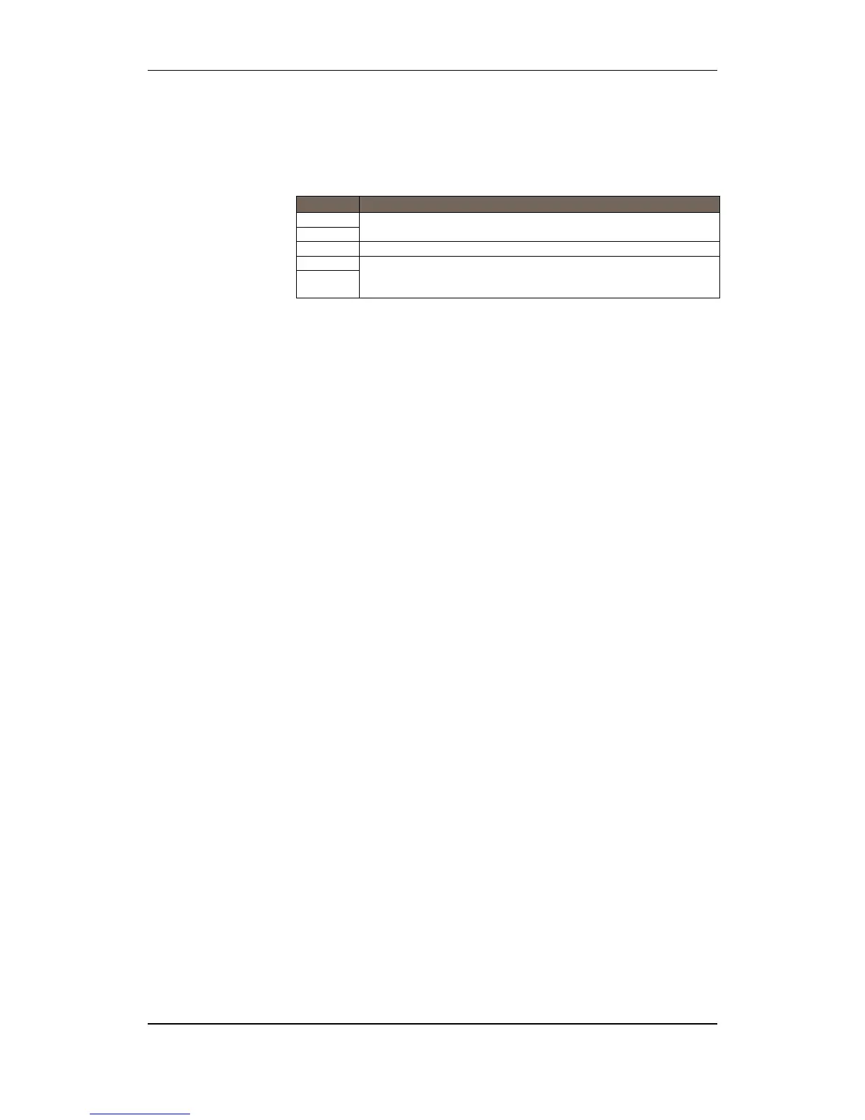
12.6 Serial Port Settings (S4)
Switch Description
S4.1 Multi purpose serial port RS485/RS422 failsafe termination,
ON/OFF
S4.2
S4.3 Multi purpose serial port RS485/RS422 line termination, ON/OFF
S4.4 RS485/RS422 mode select
RS485 mode: both switches ON,
RS422 mode: both switches OFF
S4.5
12.7 System Fault LED indicator (yellow)
The yellow System Fault indicator is lit if a system fault occurs.
The board enters this security mode if the main processor fails to
function due to hardware problems on the main board, programme
faults or faults in the file system. If such a fault occurs, the reset
switch (S1) has to be pressed to regain normal operation of the
board. If it is not possible to regain normal operation, the board
must be replaced.
12.8 Status LED indicator (red)
Not in use.
12.9 Power LED indicator (green)
The green Power LED indicator is lit when the main board is
supplied with the correct power (3,3VDC and 5VDC).
12.10 Regulated 24V Indicator (green)
The green LED indicator is lit when the regulated 24V power is OK.

 Loading...