Cable Connections
Installation Handbook, Autroprime Interactive Fire Detection System, 116-P-APRIME2-INSTAL/DGB, Rev. C, 2016-29-02,
Autronica Fire and Security AS
Page 50
9.12.2 Switch Settings
RS-485 termination and board mode switch.
Switch Description
S2.1 RS-485 3 Failsafe termination
(see description below)
S2.2
S2.3 RS-485 3 Line termination
S2.7 BUR-200 Master/Slave select (ON: Master,
OFF: Slave)
S2.8 Toggle function: impedance versus light
intensity.
Switch Settings Failsafe and Line Termination
Master and the last* Slave: The switches S2.1, S2.2 and S2.3 are to
be set to ON.
Other Slaves: The switches S2.1, S2.2 and S2.3 are to be set to
OFF.
*Refer to the next chapter: Connection of Master and Slave Mimic
Drivers.
X2 Panel Bus Address Switch
If S2.7 is set to Master, X2 sets the panel bus address. If S2.7 is
set as slave, X2 sets the RS-485 daisy-chain slave address. The
range for the switch is 1-9.
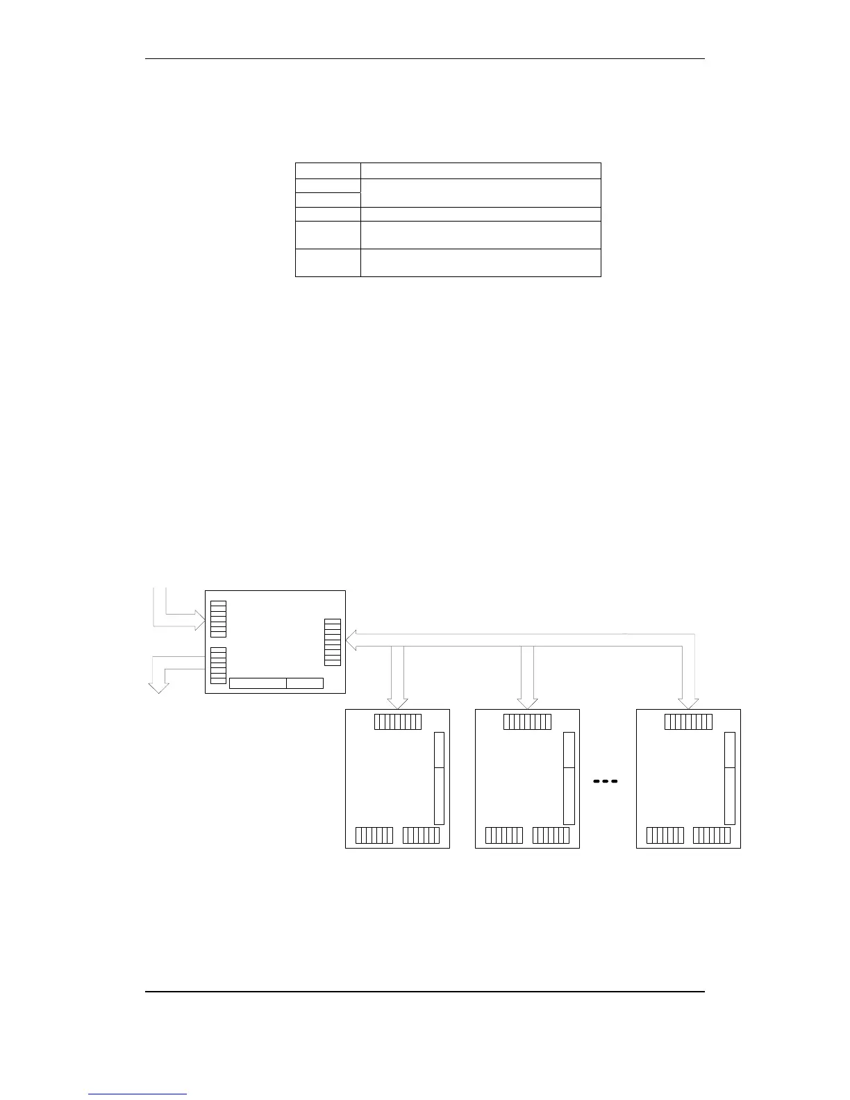
9.12.3 Connection of Master and Slave Mimic Drivers
TuBUS in
TuBUS out
BUR-200, Master mode
(Set by DIP switch)
V1+
V1-
V2+
V2-
A
B
scr
V1+
V1-
V2+
V2-
A
B
scr
V1+
V1-
V2+
V2-
A1
B1
0
A2
B2
32 out 8 mon in
BUR-200, Slave mode
Address 1
V1+
V1-
V2+
V2-
A
B
scr
V1+
V1-
V2+
V2-
A
B
scr
V1+
V1-
V2+
V2-
A1
B1
0
A2
B2
32 out 8 mon in
BUR-200, Slave mode
Address 2
V1+
V1-
V2+
V2-
A
B
scr
V1+
V1-
V2+
V2-
A
B
scr
V1+
V1-
V2+
V2-
A1
B1
0
A2
B2
32 out 8 mon in
BUR-200, Slave mode
Address 8
V1+
V1-
V2+
V2-
A
B
scr
V1+
V1-
V2+
V2-
A
B
scr
V1+
V1-
V2+
V2-
A1
B1
0
A2
B2
32 out 8 mon in
RS-485 Multidrop
7

 Loading...